9 psc module n input control register - pmicn – Rainbow Electronics ATmega64C1 User Manual
Page 154
154
7647A–AVR–02/08
ATmega32/64/M1/C1
14.16.9
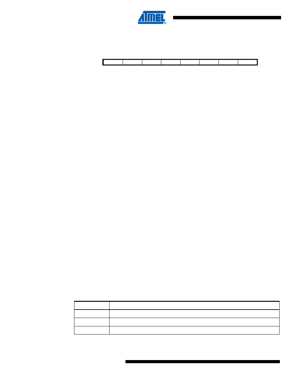
PSC Module n Input Control Register – PMICn
The Input Control Registers are used to configure the 2 PSC’s Retrigger/Fault block A & B. The
2 blocks are identical, so they are configured on the same way.
• Bit 7 – POVENn : PSC Module n Overlap Enable
Set this bit to disactivate the Overlap Protection. See the Section “Overlap Protection”,
page 141.
• Bit 6 – PISELn : PSC Module n Input Select
Clear this bit to select PSCINn as module n input.
Set this bit to select Comparator n output as module n input.
• Bit 5 –PELEVn : PSC Module n Input Level Selector
When this bit is clear, the low level of selected input generates the significative event for fault
function .
When this bit is set, the high level of selected input generates the significative event for fault
function.
• Bit 4 – PFLTEn : PSC Module n Input Filter Enable
Setting this bit (to one) activates the Input Noise Canceler. When the noise canceler is activated,
the input from the input pin is filtered. The filter function requires four successive equal valued
samples of the input pin for changing its output. The Input is therefore delayed by four oscillator
cycles when the noise canceler is enabled.
• Bit 3 – PAOCn : PSC Module n 0 Asynchronous Output Control
When this bit is clear, Fault input can act directly to PSC module n outputs A & B. See
Section “PSC Input Configuration”, page 144.
• Bit 2:0 – PRFMn2:0: PSC Module n Input Mode
These three bits define the mode of operation of the PSC inputs.
Table 14-12. Input Mode Operation
Bit
7
6
5
4
3
2
1
0
POVENn
PISELn
PELEVn
PFLTEn
PAOCn
PRFMn2
PRFMn1
PRFMn0
PMICn
Read/Write
R/W
R/W
R/W
R/W
R/W
R/W
R/W
R/W
Initial Value
0
0
0
0
0
0
0
0
PRFMn2:0
Description
000b
No action, PSC Input is ignored
001b
Disactivate module n Outputs A
010b
Disactivate module n Output B