Rainbow Electronics ATmega64C1 User Manual
Page 256
256
7647A–AVR–02/08
ATmega32/64/M1/C1
ATmega32/64/M1/C1 proposes to have an external resistor used in conjunction with the Current
Source. The device measures the voltage to the boundaries of the resistance via the Analog to
Digital converter. The resulting voltage defines the physical address that the communication
handler will use when the node will participate in LIN communication.
In automotive applications, distributed voltages are very disturbed. The internal Current Source
solution of ATmega32/64/M1/C1 immunizes the address detection against any kind of voltage
variations.
Note:
1. 5V range: Max R
load
30K
Ω
3V range: Max R
load
15K
Ω
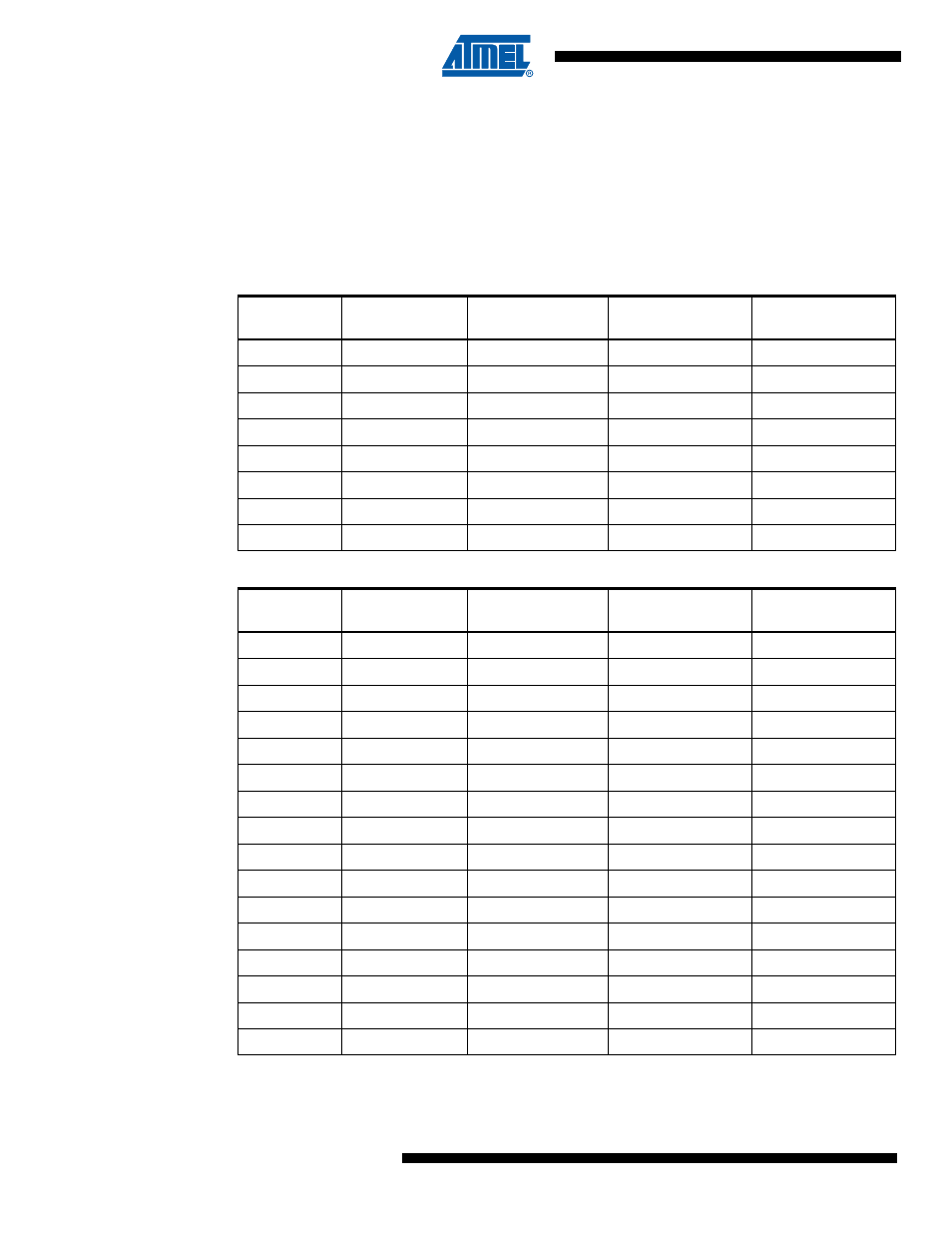
Table 19-1.
Example of Resistor Values(±5%) for a 8-address System (AVcc = 5V
)
Physical
Address
Resistor Value
R
load
(Ohm)
Minimum Voltage
Measured (V)
Typical Voltage
Measured (V)
Maximum Voltage
Measured (V)
0
1 000
0.1
1
2 200
0.22
2
3 300
0.33
3
4 700
0.47
4
6 800
0.68
5
10 000
1
6
15 000
1.5
7
22 000
2.2
Table 19-2.
Example of Resistor Values(±1%) for a 16-address System (AVcc = 5V
Physical
Address
Resistor Value
R
load
(Ohm)
Minimum Voltage
Measured (V)
Typical Voltage
Measured (V)
Maximum Voltage
Measured (V)
0
2 000
0.2
1
2 400
0.24
2
2 700
0.27
3
3 300
0.33
4
3 900
0.39
5
4 700
0.47
6
5 600
0.56
7
6 800
0.68
8
8 200
0.82
9
9 100
0.91
10
11 000
1.1
11
13 000
1.3
12
16 000
1.6
13
18 000
1.8
14
20 000
2
15
24 000
2.4