2 fuse bits – Rainbow Electronics ATmega64C1 User Manual
Page 290
290
7647A–AVR–02/08
ATmega32/64/M1/C1
Notes:
1. Program the Fuse bits and Boot Lock bits before programming the LB1 and LB2.
2. “1” means unprogrammed, “0” means programmed
24.2
Fuse Bits
The ATmega32/64/M1/C1 has three Fuse bytes.
-
describe briefly the
functionality of all the fuses and how they are mapped into the Fuse bytes. Note that the fuses
are read as logical zero, “0”, if they are programmed.
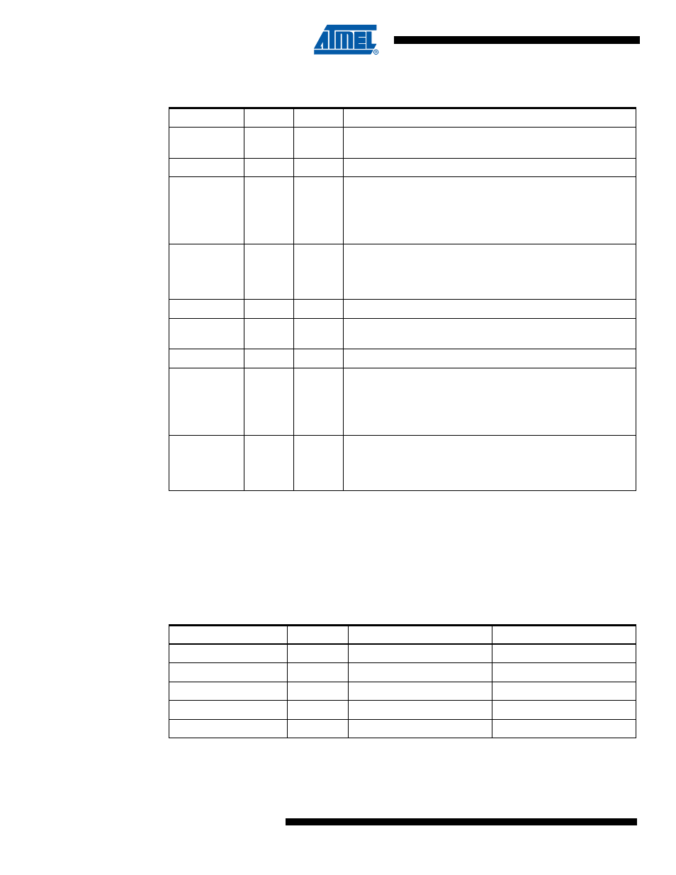
Table 24-3.
Lock Bit Protection Modes
BLB0 Mode
BLB02
BLB01
1
1
1
No restrictions for SPM or LPM accessing the Application
section.
2
1
0
SPM is not allowed to write to the Application section.
3
0
0
SPM is not allowed to write to the Application section, and LPM
executing from the Boot Loader section is not allowed to read
from the Application section. If Interrupt Vectors are placed in
the Boot Loader section, interrupts are disabled while executing
from the Application section.
4
0
1
LPM executing from the Boot Loader section is not allowed to
read from the Application section. If Interrupt Vectors are placed
in the Boot Loader section, interrupts are disabled while
executing from the Application section.
BLB1 Mode
BLB12
BLB11
1
1
1
No restrictions for SPM or LPM accessing the Boot Loader
section.
2
1
0
SPM is not allowed to write to the Boot Loader section.
3
0
0
SPM is not allowed to write to the Boot Loader section, and LPM
executing from the Application section is not allowed to read
from the Boot Loader section. If Interrupt Vectors are placed in
the Application section, interrupts are disabled while executing
from the Boot Loader section.
4
0
1
LPM executing from the Application section is not allowed to
read from the Boot Loader section. If Interrupt Vectors are
placed in the Application section, interrupts are disabled while
executing from the Boot Loader section.
Table 24-4.
Extended Fuse Byte
Extended Fuse Byte
Bit No
Description
Default Value
-
7
-
1 (unprogrammed)
-
6
-
1 (unprogrammed)
PSCRB
5
PSC Reset Behaviour
1 (unprogrammed)
PSCRVA
4
PSCOUTnA Reset Value
1 (unprogrammed)
PSCRVB
3
PSCOUTnB Reset Value
1 (unprogrammed)