1 oscillator calibration register - osccal – Rainbow Electronics ATmega64C1 User Manual
Page 33
33
7647A–AVR–02/08
ATmega32/64/M1/C1
ibrates the RC Oscillator. The accuracy of this calibration is shown as Factory calibration in
By changing the OSCCAL register from SW, see
“Oscillator Calibration Register – OSCCAL” on
, it is possible to get a higher calibration accuracy than by using the factory calibration.
The accuracy of this calibration is shown as User calibration in
“Clock Characteristics” on page
.
When this Oscillator is used as the chip clock, the Watchdog Oscillator will still be used for the
Watchdog Timer and for the Reset Time-out. For more information on the pre-programmed cali-
bration value, see the section .
Notes:
1. The device is shipped with this option selected.
2. If 8 MHz frequency exceeds the specification of the device (depends on V
CC
), the CKDIV8
Fuse can be programmed in order to divide the internal frequency by 8.
When this Oscillator is selected, start-up times are determined by the SUT Fuses as shown in
Note:
1. If the RSTDISBL fuse is programmed, this start-up time will be increased to
14CK + 4.1 ms to ensure programming mode can be entered.
2.
The device is shipped with this option selected.
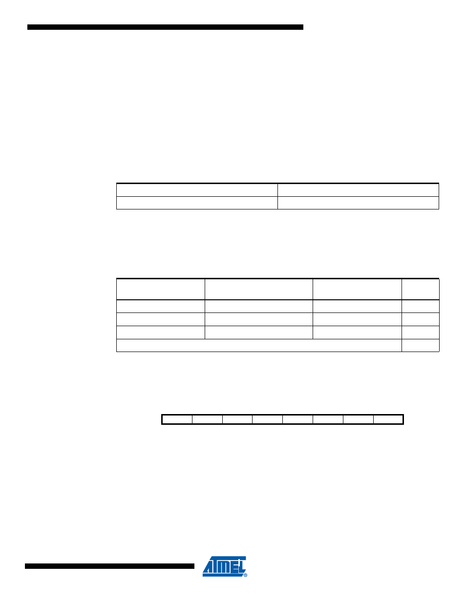
5.5.1
Oscillator Calibration Register – OSCCAL
• Bits 7..0 – CAL7..0: Oscillator Calibration Value
The Oscillator Calibration Register is used to trim the Calibrated Internal RC Oscillator to
remove process variations from the oscillator frequency. The factory-calibrated value is automat-
ically written to this register during chip reset, giving an oscillator frequency of 8.0 MHz at 25°C.
The application software can write this register to change the oscillator frequency. The oscillator
can be calibrated to any frequency in the range 7.3 - 8.1 MHz within ±1% accuracy. Calibration
outside that range is not guaranteed.
Note that this oscillator is used to time EEPROM and Flash write accesses, and these write
times will be affected accordingly. If the EEPROM or Flash are written, do not calibrate to more
than 8.8 MHz. Otherwise, the EEPROM or Flash write may fail.
Table 5-5.
Internal Calibrated RC Oscillator Operating Modes
Frequency Range (MHz)
CKSEL3..0
7.3 - 8.1
0010
Table 5-6.
Start-up times for the internal calibrated RC Oscillator clock selection
Power Conditions
Start-up Time from Power-
down and Power-save
Additional Delay from
Reset (V
CC
= 5.0V)
SUT1..0
BOD enabled
6 CK
14CK
00
Fast rising power
6 CK
14CK + 4.1 ms
01
Slowly rising power
6 CK
14CK + 65 ms
10
Reserved
11
Bit
7
6
5
4
3
2
1
0
CAL7
CAL6
CAL5
CAL4
CAL3
CAL2
CAL1
CAL0
OSCCAL
Read/Write
R/W
R/W
R/W
R/W
R/W
R/W
R/W
R/W
Initial Value
Device Specific Calibration Value