2 pll control and status register - pllcsr, 7 128 khz internal oscillator, 8 external clock – Rainbow Electronics ATmega64C1 User Manual
Page 35
35
7647A–AVR–02/08
ATmega32/64/M1/C1
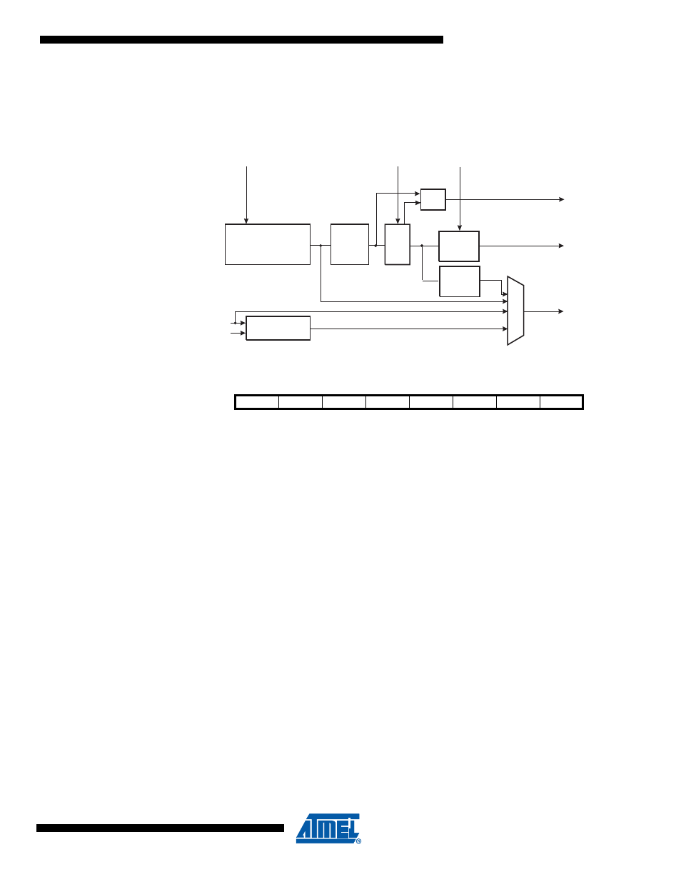
Figure 5-3.
PCK Clocking System
5.6.2
PLL Control and Status Register – PLLCSR
• Bit 7..3 – Res: Reserved Bits
These bits are reserved bits in the ATmega32/64/M1/C1 and always read as zero.
• Bit 2 – PLLF: PLL Factor
The PLLF bit is used to select the division factor of the PLL.
If PLLF is set, the PLL output is 64MHz.
If PLLF is clear, the PLL output is 32MHz.
• Bit 1 – PLLE: PLL Enable
When the PLLE is set, the PLL is started and if not yet started the internal RC Oscillator is
started as PLL reference clock. If PLL is selected as a system clock source the value for this bit
is always 1.
• Bit 0 – PLOCK: PLL Lock Detector
When the PLOCK bit is set, the PLL is locked to the reference clock, and it is safe to enable
CLK
PLL
for Fast Peripherals. After the PLL is enabled, it takes about 100 ms for the PLL to lock.
5.7
128 kHz Internal Oscillator
The 128 kHz internal Oscillator is a low power Oscillator providing a clock of 128 kHz. The fre-
quency is nominal at 3V and 25
°
C. This clock is used by the Watchdog Oscillator.
5.8
External Clock
To drive the device from an external clock source, XTAL1 should be driven as shown in
. To run the device on an external clock, the CKSEL Fuses must be programmed to “0000”.
2.
This value do not provide a proper restart ; do not use PD in this clock scheme
3.
This value do not provide a proper restart ; do not use PD in this clock scheme
8 MHz
RC OSCILLATOR
OSCCAL
XTAL1
XTAL2
OSCILLATORS
DIVIDE
BY 8
DIVIDE
BY 2
CK
PLL
64x
PLLE
Lock
Detector
PLOCK
SOURCE
PLLF
DIVIDE
BY 4
CLK
PLL
Bit
7
6
5
4
3
2
1
0
$29 ($29)
–
–
–
–
–
PLLF
PLLE
PLOCK
PLLCSR
Read/Write
R
R
R
R
R
R/W
R/W
R
Initial Value
0
0
0
0
0
0
0/1
0