3 data length in rx response, 4 data length in tx response – Rainbow Electronics ATmega64C1 User Manual
Page 214
214
7647A–AVR–02/08
ATmega32/64/M1/C1
17.5.7.3
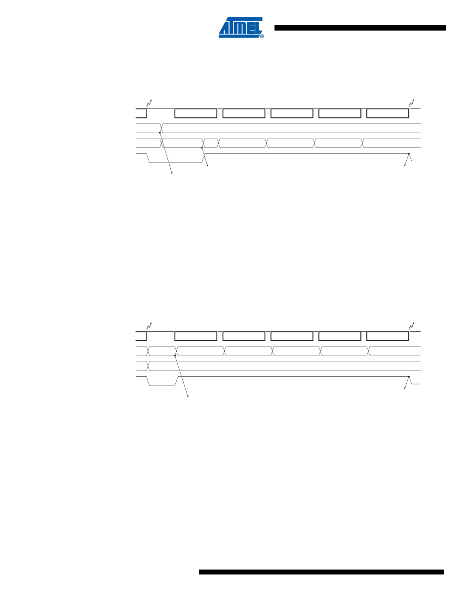
Data Length in Rx Response
Figure 17-9. LIN2.1 - Rx Response - No error
•
The user initializes LRXDL field before setting the Rx Response command,
•
After setting the Rx Response command, LTXDL is reset by hardware,
•
LRXDL field will remain unchanged during Rx (during busy signal),
•
LTXDL field will count the number of received bytes (during busy signal),
•
If an error occurs, Rx stops, the corresponding error flag is set and LTXDL will give the num-
ber of received bytes without error,
•
If no error occurs, LRXOK is set after the reception of the CHECKSUM, LRXDL will be
unchanged (and LTXDL = LRXDL).
17.5.7.4
Data Length in Tx Response
Figure 17-10. LIN1.3 - Tx Response - No error
•
The user initializes LTXDL field before setting the Tx Response command,
•
After setting the Tx Response command, LRXDL is reset by hardware,
•
LTXDL will remain unchanged during Tx (during busy signal),
•
LRXDL will count the number of transmitted bytes (during busy signal),
•
If an error occurs, Tx stops, the corresponding error flag is set and LRXDL will give the num-
ber of transmitted bytes without error,
•
If no error occurs, LTXOK is set after the transmission of the CHECKSUM, LTXDL will be
unchanged (and LRXDL = LTXDL).
DATA-0
DATA-1
DATA-2
DATA-3
CHECKSUM
LINDLR=0x?4
LCMD2..0=000
b
LIN bus
LRXDL (*)
4
1
?
0
LBUSY
LTXDL (*)
2
3
4
1
st
Byte
2
nd
Byte
3
rd
Byte
4
th
Byte
LIDOK
LRXOK
LCMD=Rx Response
(*) : LRXDL & LTXDL updated by user
DATA-0
DATA-1
DATA-2
DATA-3
CHECKSUM
LCMD2..0=000
b
LIN bus
LBUSY
1
st
Byte
2
nd
Byte
3
rd
Byte
4
th
Byte
LIDOK
LTXOK
1
4
0
LRXDL (*)
2
3
4
LCMD=Tx Response
(*) : LRXDL & LTXDL updated by Rx Response or Tx Response task
LTXDL (*)
4