3 clock characteristics, 1 calibrated internal rc oscillator accuracy, 4 external clock drive characteristics – Rainbow Electronics ATmega64C1 User Manual
Page 312: 5 maximum speed vs. vcc, 5 maximum speed vs. v
312
7647A–AVR–02/08
ATmega32/64/M1/C1
25.3
Clock Characteristics
25.3.1
Calibrated Internal RC Oscillator Accuracy
25.4
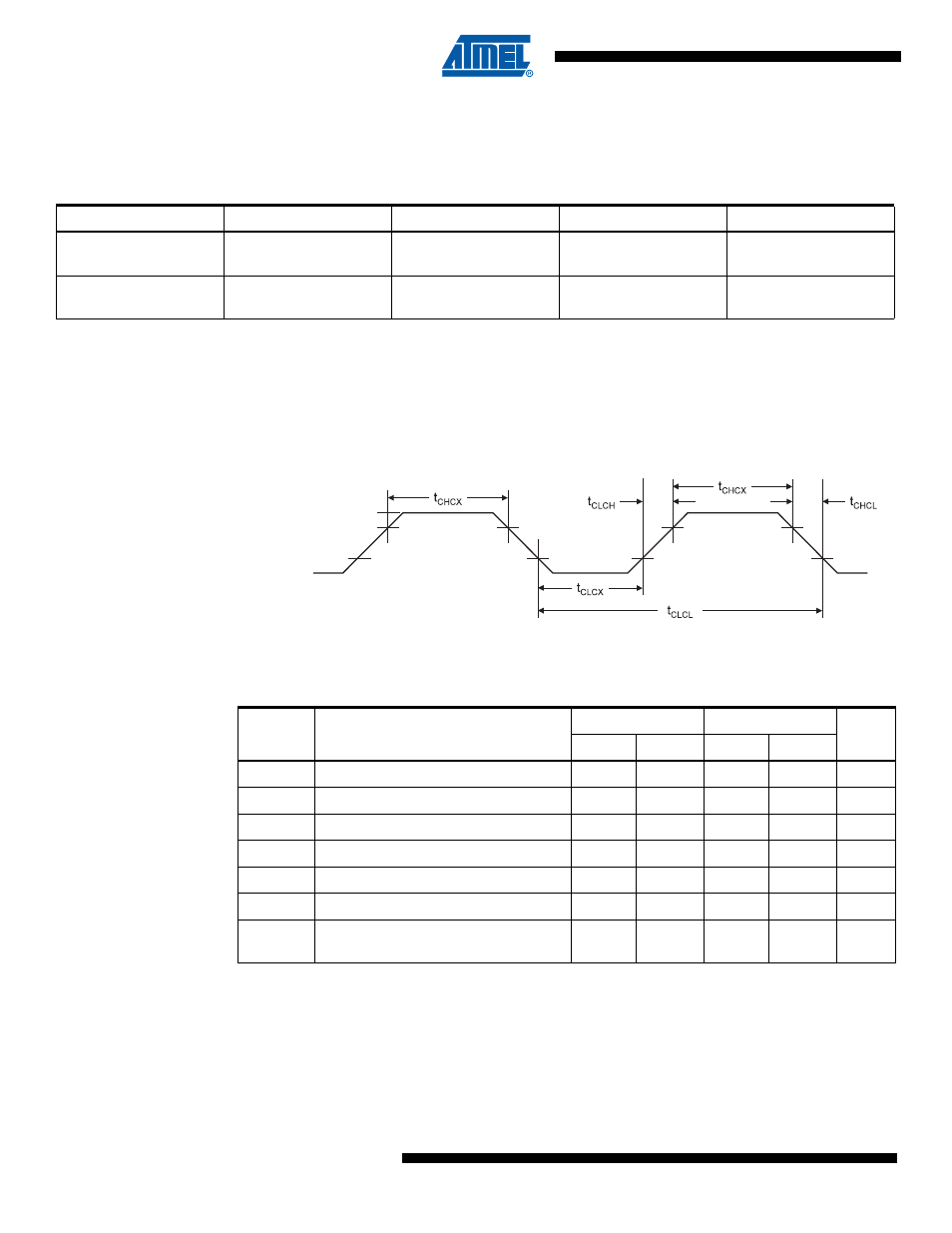
External Clock Drive Characteristics
Figure 25-1. External Clock Drive Waveforms
25.5
Maximum Speed vs. V
CC
Maximum frequency is depending on V
CC.
As shown in
, the Maximum Frequency
equals 8MHz when V
CC
is between 2.7V and 4.5V and equals 16MHz when V
CC
is between 4.5V
and 5.5V.
Table 25-1.
Calibration Accuracy of Internal RC Oscillator
Frequency
V
CC
Temperature Calibration
Accuracy
Factory
Calibration
8.0 MHz
3V
25
°
C
±1%
User
Calibration
7.3 - 8.1 MHz
2.7V - 5.5V
-40
°
C - 125
°
C
±10%
Table 2. External Clock Drive
Symbol
Parameter
V
CC
= 2.7 - 5.5V
V
CC
= 4.5 - 5.5V
Units
Min.
Max.
Min.
Max.
1/t
CLCL
Oscillator Frequency
0
8
0
16
MHz
t
CLCL
Clock Period
125
62.5
ns
t
CHCX
High Time
50
25
ns
t
CLCX
Low Time
50
25
ns
t
CLCH
Rise Time
1.6
0.5
μ
s
t
CHCL
Fall Time
1.6
0.5
μ
s
Δ
t
CLCL
Change in period from one clock cycle
to the next
2
2
%
V
IL1
V
IH1