5 busy signal, 1 busy signal in lin mode, 2 busy signal in uart mode – Rainbow Electronics ATmega64C1 User Manual
Page 211
211
7647A–AVR–02/08
ATmega32/64/M1/C1
The LIN configuration is independent of the programmed LIN protocol.
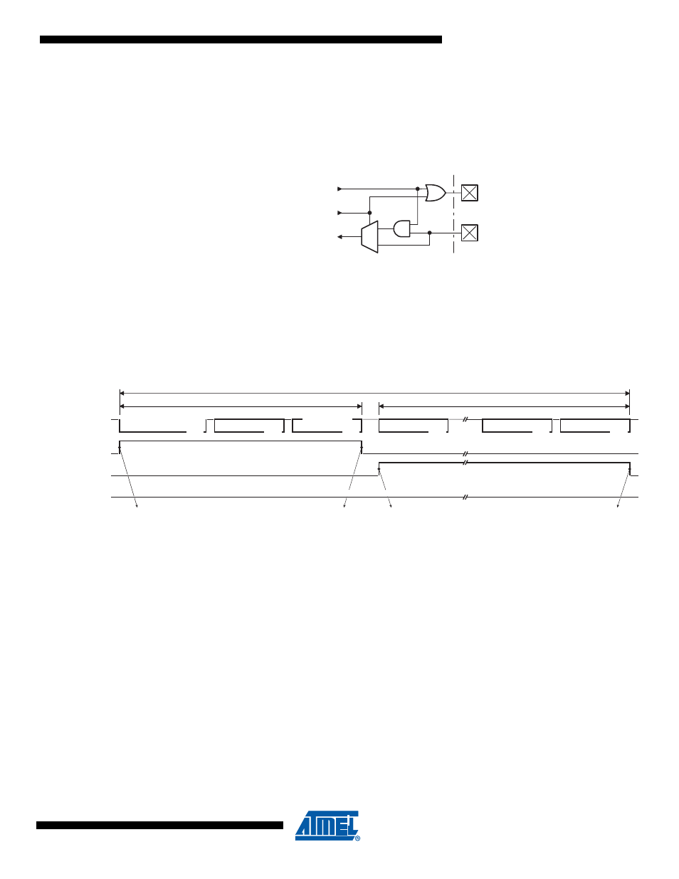
The listening mode connects the internal Tx LIN and the internal Rx LIN together. In this mode,
the TXLIN output pin is disabled and the RXLIN input pin is always enabled. The same scheme
is available in UART mode.
Figure 17-6. Listening Mode
17.5.5
Busy Signal
LBUSY bit flag in LINSIR register is the image of the BUSY signal. It is set and cleared by hard-
ware. It signals that the controller is busy with LIN or UART communication.
17.5.5.1
Busy Signal in LIN Mode
Figure 17-7. Busy Signal in LIN Mode
When the busy signal is set, some registers are locked, user writing is not allowed:
•
“LIN Control Register” - LINCR - except LCMD[2..0], LENA & LSWRES,
•
“LIN Baud Rate Registers” - LINBRRL & LINBRRH,
•
“LIN Data Length Register” - LINDLR,
•
“LIN Identifier Register” - LINIDR,
•
“LIN Data Register” - LINDAT.
If the busy signal is set, the only available commands are:
•
LCMD[1..0] = 00
b
, the abort command is taken into account at the end of the byte,
•
LENA = 0 and/or LCMD[2] = 0, the kill command is taken into account immediately,
•
LSWRES = 1, the reset command is taken into account immediately.
Note that, if another command is entered during busy signal, the new command is not validated
and the LOVRERR bit flag of the LINERR register is set. The on-going transfer is not
interrupted.
17.5.5.2
Busy Signal in UART Mode
During the byte transmission, the busy signal is set. This locks some registers from being
written:
•
“LIN Control Register” - LINCR - except LCMD[2..0], LENA & LSWRES,
1
0
TXLIN
RXLIN
internal
Tx LIN
internal
Rx LIN
LISTEN
BREAK
Field
SYNC
Field
CHECKSUM
Field
DATA-0
Field
Field
IDENTIFIER
PROTECTED
DATA-n
Field
RESPONSE
HEADER
FRAME SLOT
LIN bus
LIDOK
Node providing the master task
Node providing a slave task
LCMD=Tx Header
LTXOK or LRXOK
LCMD=Tx or Rx Response
1) LBUSY
3) LBUSY
2) LBUSY
Node providing neither the master task, neither a slave task