10 psc interrupt mask register - pim, 11 psc interrupt flag register - pifr, Disactivate module n output a & b – Rainbow Electronics ATmega64C1 User Manual
Page 155: Disactivate all psc output, Halt psc and wait for software action
155
7647A–AVR–02/08
ATmega32/64/M1/C1
14.16.10 PSC Interrupt Mask Register – PIM
• Bit 7:4 – not use
not use.
• Bit 3 – PEVE2 : PSC External Event 2 Interrupt Enable
When this bit is set, an external event which can generates a a fault on module 2 generates also
an interrupt.
• Bit 2 – PEVE1 : PSC External Event 1 Interrupt Enable
When this bit is set, an external event which can generates a fault on module 1 generates also
an interrupt.
• Bit 1 – PEVE0 : PSC External Event 0 Interrupt Enable
When this bit is set, an external event which can generates a fault on module 0 generates also
an interrupt.
• Bit 0 – PEOPE : PSC End Of Cycle Interrupt Enable
When this bit is set, an interrupt is generated when PSC reaches the end of the whole cycle.
14.16.11 PSC Interrupt Flag Register – PIFR
• Bit 7:4 – not use
not use.
• Bit 3 – PEV2 : PSC External Event 2 Interrupt
This bit is set by hardware when an external event which can generates a fault on module 2
occurs.
Must be cleared by software by writing a one to its location.
This bit can be read even if the corresponding interrupt is not enabled (PEVE2 bit = 0).
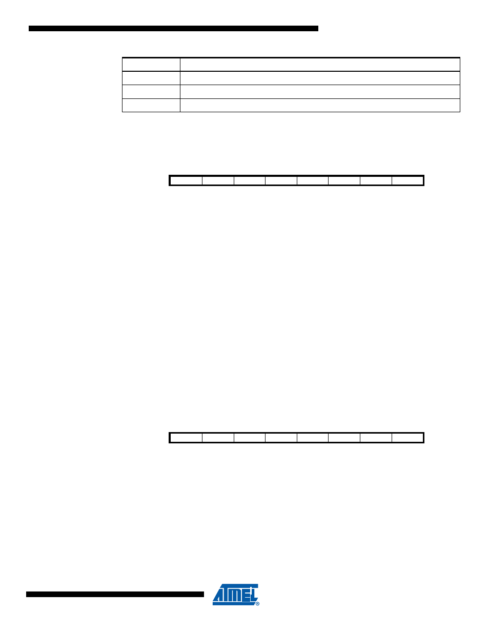
011b
Disactivate module n Output A & B
10x
Disactivate all PSC Output
11xb
Halt PSC and Wait for Software Action
PRFMn2:0
Description
Bit
7
6
5
4
3
2
1
0
-
-
-
-
PEVE2
PEVE1
PEVE0
PEOPE
PIM
Read/Write
R
R
R
R
R/W
R/W
R/W
R/W
Initial Value
0
0
0
0
0
0
0
0
Bit
7
6
5
4
3
2
1
0
-
-
-
-
PEV2
PEV1
PEV0
PEOP
PIFR
Read/Write
R
R
R
R
R/W
R/W
R/W
R/W
Initial Value
0
0
0
0
0
0
0
0