5 analog comparator status register - acsr, See “analog comparator sta – Rainbow Electronics ATmega64C1 User Manual
Page 264
264
7647A–AVR–02/08
ATmega32/64/M1/C1
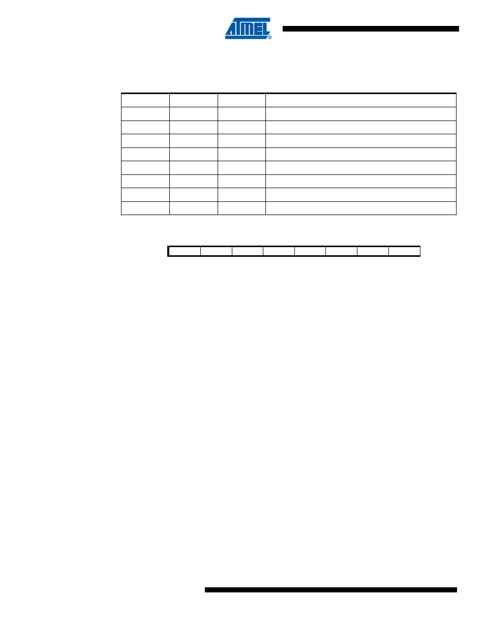
These 3 bits determine the input of the negative input of the analog comparator.
The different setting are shown in
20.4.5
Analog Comparator Status Register – ACSR
• Bit 7– AC3IF: Analog Comparator 3 Interrupt Flag Bit
This bit is set by hardware when comparator 3 output event triggers off the interrupt mode
defined by AC3IS1 and AC3IS0 bits in AC2CON register.
This bit is cleared by hardware when the corresponding interrupt vector is executed in case the
AC3IE in AC3CON register is set. Anyway, this bit is cleared by writing a logical one on it.
This bit can also be used to synchronize ADC or DAC conversions.
• Bit 6– AC2IF: Analog Comparator 2 Interrupt Flag Bit
This bit is set by hardware when comparator 2 output event triggers off the interrupt mode
defined by AC2IS1 and AC2IS0 bits in AC2CON register.
This bit is cleared by hardware when the corresponding interrupt vector is executed in case the
AC2IE in AC2CON register is set. Anyway, this bit is cleared by writing a logical one on it.
This bit can also be used to synchronize ADC or DAC conversions.
• Bit 5– AC1IF: Analog Comparator 1 Interrupt Flag Bit
This bit is set by hardware when comparator 1 output event triggers off the interrupt mode
defined by AC1IS1 and AC1IS0 bits in AC1CON register.
This bit is cleared by hardware when the corresponding interrupt vector is executed in case the
AC1IE in AC1CON register is set. Anyway, this bit is cleared by writing a logical one on it.
This bit can also be used to synchronize ADC or DAC conversions.
• Bit 4– AC0IF: Analog Comparator 0 Interrupt Flag Bit
This bit is set by hardware when comparator 0 output event triggers off the interrupt mode
defined by AC0IS1 and AC0IS0 bits in AC0CON register.
This bit is cleared by hardware when the corresponding interrupt vector is executed in case the
AC0IE in AC0CON register is set. Anyway, this bit is cleared by writing a logical one on it.
This bit can also be used to synchronize ADC or DAC conversions.
• Bit 3– AC3O: Analog Comparator 3 Output Bit
Table 20-8.
Analog Comparator 3 negative input selection
AC3M2
AC3M1
AC3M0
Description
0
0
0
“Vref”/6.40
0
0
1
“Vref”/3.20
0
1
0
“Vref”/2.13
0
1
1
“Vref”/1.60
1
0
0
Bandgap (1.1V)
1
0
1
DAC result
1
1
0
Analog Comparator Negative Input (ACMPM pin)
1
1
1
Reserved
Bit
7
6
5
4
3
2
1
0
AC3IF
AC2IF
AC1IF
AC0IF
AC3O
AC2O
AC1O
AC0O
ACSR
Read/Write
R/W
R/W
R/W
R/W
R
R
R
R
Initial Value
0
0
0
0
0
0
0
0