2 operation, 3 starting a conversion – Rainbow Electronics ATmega64C1 User Manual
Page 267
267
7647A–AVR–02/08
ATmega32/64/M1/C1
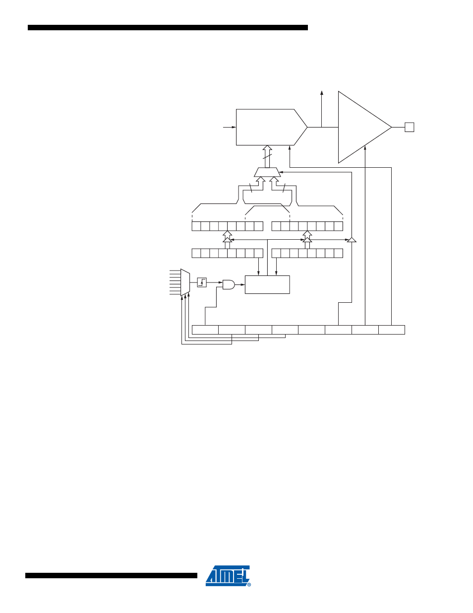
Figure 21-1. Digital to Analog Converter Block Schematic
21.2
Operation
The Digital to Analog Converter generates an analog signal proportional to the value of the DAC
registers value.
In order to have an accurate sampling frequency control, there is the possibility to update the
DAC input values through different trigger events.
21.3
Starting a Conversion
The DAC is configured thanks to the DACON register. As soon as the DAEN bit in DACON reg-
ister is set, the DAC converts the value present on the DACH and DACL registers in accordance
with the register DACON setting.
Alternatively, a conversion can be triggered automatically by various sources. Auto Triggering is
enabled by setting the DAC Auto Trigger Enable bit, DAATE in DACON. The trigger source is
selected by setting the DAC Trigger Select bits, DATS in DACON (See description of the DATS
bits for a list of the trigger sources). When a positive edge occurs on the selected trigger signal,
the DAC converts the value present on the DACH and DACL registers in accordance with the
register DACON setting. This provides a method of starting conversions at fixed intervals. If the
trigger signal is still set when the conversion completes, a new conversion will not be started. If
another positive edge occurs on the trigger signal during conversion, the edge will be ignored.
Note that an interrupt flag will be set even if the specific interrupt is disabled or the Global Inter-
DAC
Output
Driver
DALA
DAOE
DAEN
-
DAATE
DATS2
DATS1
DATS0
10
DACH
DACL
DACON
10
10
1
0
VRef
D2A pin
DAC
Result
Update DAC
Trigger
DAC Low bits
DAC High bits
Edge
Detector
Sources