9 clock output buffer, 10 system clock prescaler, Mmed. see – Rainbow Electronics ATmega64C1 User Manual
Page 36
36
7647A–AVR–02/08
ATmega32/64/M1/C1
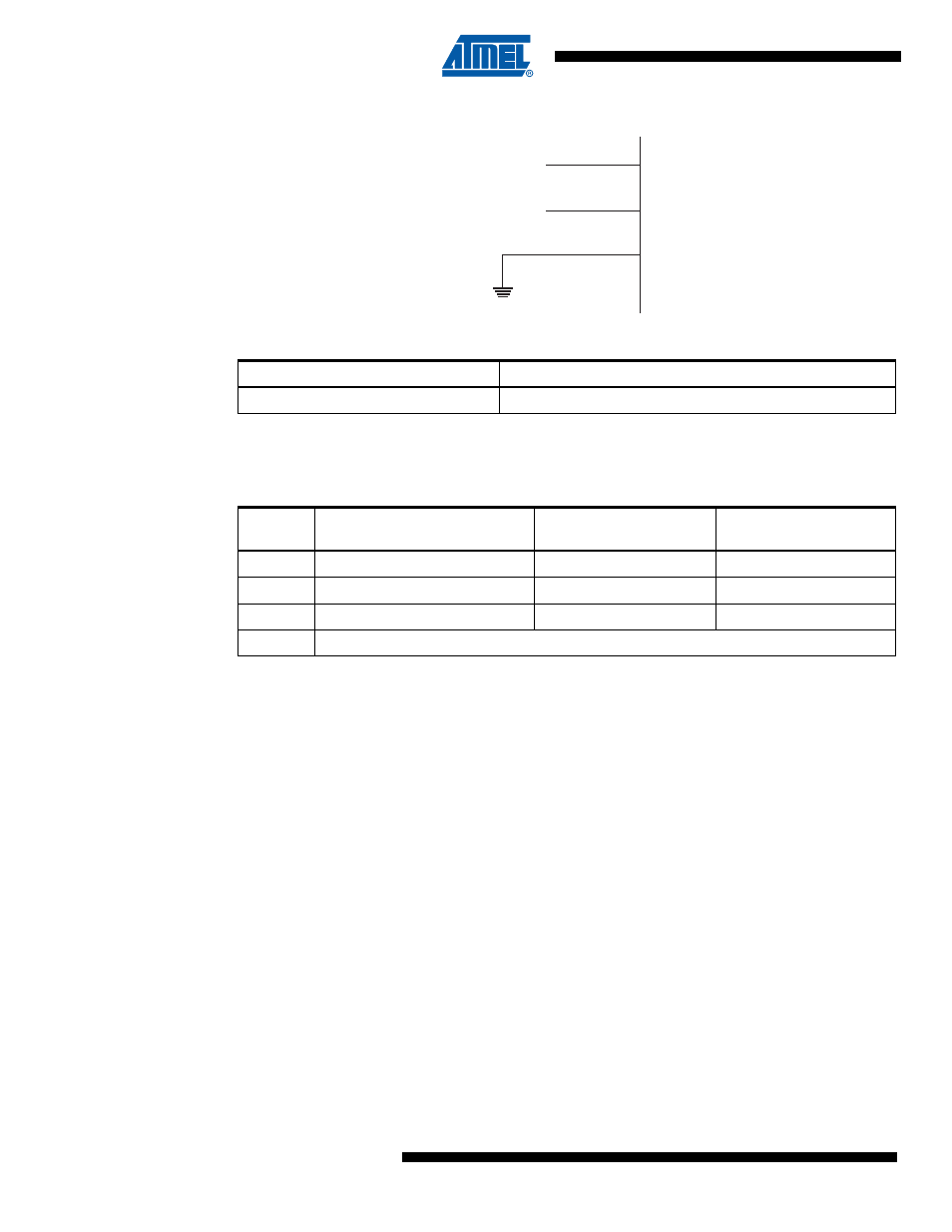
Figure 5-4.
External Clock Drive Configuration
When this clock source is selected, start-up times are determined by the SUT Fuses as shown in
.
When applying an external clock, it is required to avoid sudden changes in the applied clock fre-
quency to ensure stable operation of the MCU. A variation in frequency of more than 2% from
one clock cycle to the next can lead to unpredictable behavior. It is required to ensure that the
MCU is kept in Reset during such changes in the clock frequency.
Note that the System Clock Prescaler can be used to implement run-time changes of the internal
clock frequency while still ensuring stable operation. Refer to
“System Clock Prescaler” on page
for details.
5.9
Clock Output Buffer
When the CKOUT Fuse is programmed, the system Clock will be output on CLKO. This mode is
suitable when chip clock is used to drive other circuits on the system. The clock will be output
also during reset and the normal operation of I/O pin will be overridden when the fuse is pro-
grammed. Any clock source, including internal RC Oscillator, can be selected when CLKO
serves as clock output. If the System Clock Prescaler is used, it is the divided system clock that
is output (CKOUT Fuse programmed).
5.10
System Clock Prescaler
The ATmega32/64/M1/C1 system clock can be divided by setting the Clock Prescale Register –
CLKPR. This feature can be used to decrease power consumption when the requirement for
processing power is low. This can be used with all clock source options, and it will affect the
clock frequency of the CPU and all synchronous peripherals. clk
I/O
, clk
ADC
, clk
CPU
, and clk
FLASH
are divided by a factor as shown in
.
Table 5-8.
External Clock Frequency
CKSEL3..0
Frequency Range
0000
0 - 16 MHz
Table 5-9.
Start-up Times for the External Clock Selection
SUT1..0
Start-up Time from Power-
down and Power-save
Additional Delay from
Reset (V
CC
= 5.0V)
Recommended Usage
00
6 CK
14CK
BOD enabled
01
6 CK
14CK + 4.1 ms
Fast rising power
10
6 CK
14CK + 65 ms
Slowly rising power
11
Reserved
XTAL2
XTAL1
GND
NC
External
Clock
Signal