Rainbow Electronics W90N745CDG User Manual
Page 53
W90N745CD/W90N745CDG
- 48 -
Continued.
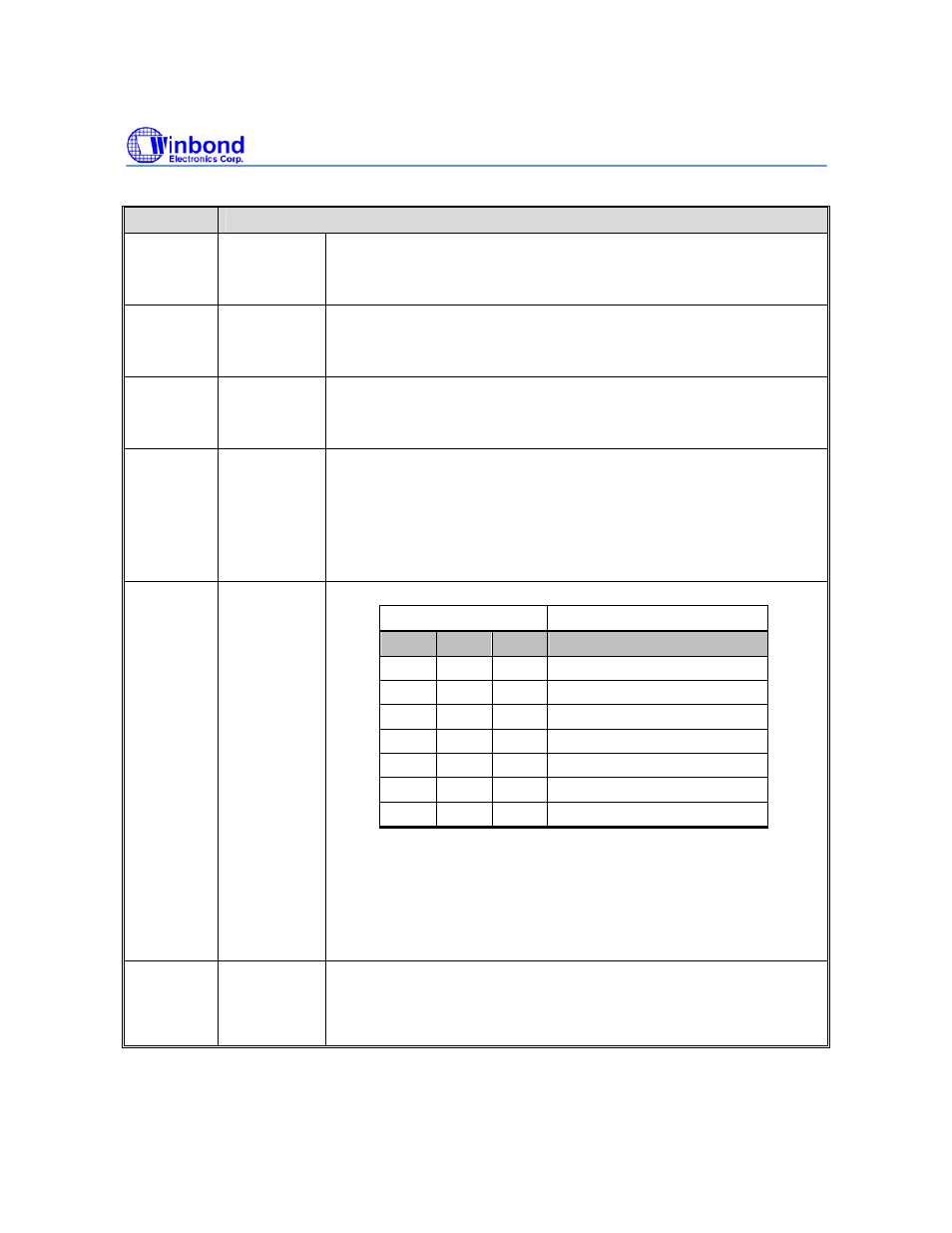
BITS
DESCRIPTION
[7] USBH
USB host clock enable bit
0 = Disable USB host controller clock
1 = Enable USB host controller clock
[6] TIMER
Timer clock enable bit
0 = Disable timer clock
1 = Enable timer clock
[5] UART0
UART0 controller clock enable bit
0 = Disable UART0 controller clock
1 = Enable UART0 controller clock
[4] ECLKS
External clock select
0 = External clock from EXTAL pin is used as system clock
1 = PLL output clock is used as system clock
After power on reset, the content of ECLKS is the Power-On
Setting value. You can program this bit to change the system clock
source.
[3:1] CLKS
PLL output clock select
CLKS [3:1]
System clock
0
0
0
58.594 KHz*
0 0 1
24
MHz
0 1 0
48
MHz
0 1 1
60
MHz
1 0 0
80
MHz
1 0 1
RESERVED
1 1 0
RESERVED
1 1 1
RESERVED
Note:
1. This values are based on PLL output(FOUT) is 480MHz.
2. When 24Mhz ~ 80MHz is selected, the ECLKS bit must be set to
1.
3. About 58.594KHz setting, two steps are needed. First, clear
ECLKS bit, and then clear CLKS.
[0]
RESET
Software Reset bit
This is a software reset control bit. Set logic 1 to generate an
internal reset pulse. This bit is auto-clear to logic 0 at the end of
the reset pulse.