Rainbow Electronics W90N745CDG User Manual
Page 278
W90N745CD/W90N745CDG
Publication Release Date: September 22, 2006
-
273
-
Revision
A2
BITS
DESCRIPTIONS
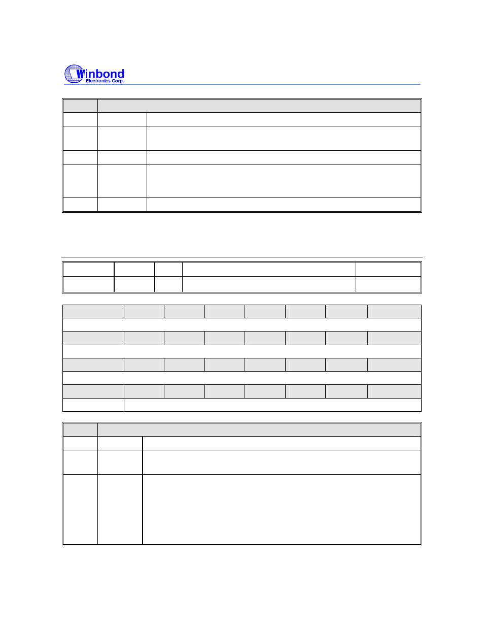
[31:6] Reserved
-
[5] DSR#
Complement version of data set ready (DSR#) input
(This bit is selected by IP)
[4:2] Reserved
-
[1] DDSR
DSR# State Change (This bit is selected by IP)
This bit is set whenever DSR# input has changed state, and it will be reset
if the CPU reads the MSR.
[0] Reserved
-
Whenever any of MSR [3:0] is set to logic 1, a Modem Status Interrupt is generated if IER[3]=1. Writing
MSR is a null operation (not suggested).
UART Time Out Register (UART_TOR)
REGISTER OFFSET R/W
DESCRIPTION
RESET
VALUE
UART_TOR
0x1C
R/W Time Out Register
0x0000_0000
31
30
29
28
27
26
25
24
Reserved
23
22
21
20
19
18
17
16
Reserved
15
14
13
12
11
10
9
8
Reserved
7
6
5
4
3
2
1
0
TOIE
TOIC
BITS
DESCRIPTIONS
[31:8] Reserved
-
[7] TOIE
Time Out Interrupt Enable
The feature of receiver time out interrupt is enabled when TOR [7] = IER[0] = 1.
[6:0] TOIC
Time Out Interrupt Comparator
The time out counter resets and starts counting (the counting clock = baud
rate) whenever the RX FIFO receives a new data word. Once the content of
time out counter (TOUT_CNT) is equal to that of time out interrupt
comparator (TOIC), a receiver time out interrupt (Irpt_TOUT) is generated if
TOR [7] = IER [0] = 1. A new incoming data word or RX FIFO empty clears
Irpt_TOUT.