Esc gs # m n n1 n2 n3 n4 lf nul – Star Micronics Line Thermal/Dot Printer User Manual
Page 97
Rev. 0.00
3-85
STAR Line Mode Command Specifications
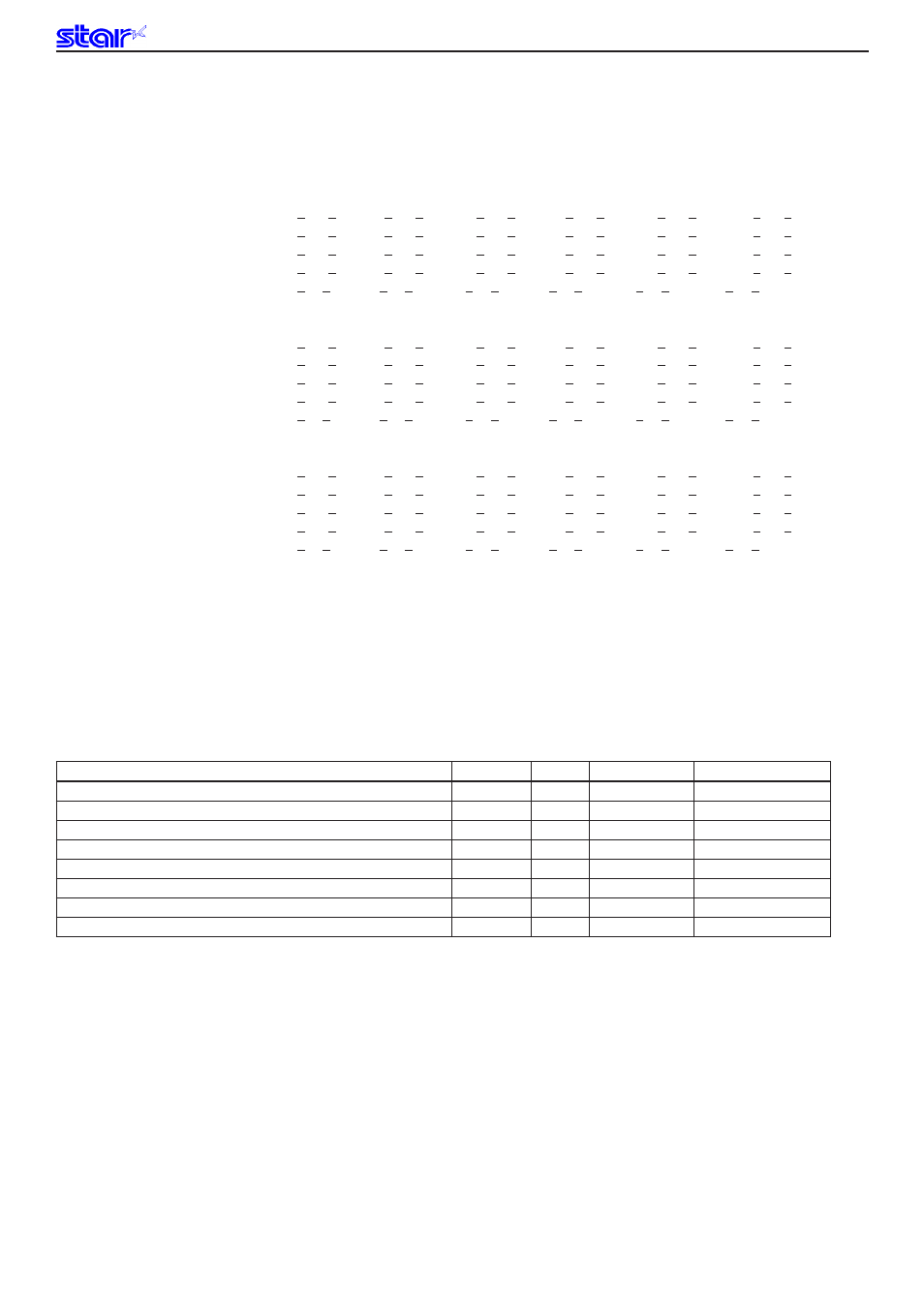
ESC GS # m N n1 n2 n3 n4 LF NUL
[Name] Set memory switch
[Code]
ASCII
ESC
GS
#
m
N n1
n2
n3
n4 LF
NUL
Hexadecimal
1B
1D
23
m
N n1
n2
n3
n4 0A
00
Decimal
27
29
35
m
N n1
n2
n3
n4
10
0
[Defined Area]
Thermal
: m = 87, 84, 44, 43, 45, 64, 75, 76 (m = “W”, “T”, “,”, “+”, “-”, “@”, “K”, “L”)
48 ≤ n1 ≤ 57 (”0” ≤ n1 ≤ “9”), 65 ≤ n1 ≤ 70 (”A” ≤ n1 ≤ “F”), 97 ≤ n1 ≤ 102 (“a” ≤ n1 ≤ “f”)
48 ≤ n2 ≤ 57 (”0” ≤ n2 ≤ “9”), 65 ≤ n2 ≤ 70 (”A” ≤ n2 ≤ “F”), 97 ≤ n2 ≤ 102 (“a” ≤ n1 ≤ “f”)
48 ≤ n3 ≤ 57 (”0” ≤ n3 ≤ “9”), 65 ≤ n3 ≤ 70 (”A” ≤ n3 ≤ “F”), 97 ≤ n3 ≤ 102 (“a” ≤ n1 ≤ “f”)
48 ≤ n4 ≤ 57 (”0” ≤ n4 ≤ “9”), 65 ≤ n4 ≤ 70 (”A” ≤ n4 ≤ “F”), 97 ≤ n4 ≤ 102 (“a” ≤ n1 ≤ “f”)
48 ≤ N ≤ 57 (”0” ≤ N ≤ “9”), 65 ≤ N ≤ 72 (”A” ≤ N ≤ “F”), 97 ≤ N ≤ 104 (“a” ≤ N ≤ “h”)
N = 85 (U) User defined region
Slip
: m = 87, 84, 44, 43, 45, 64, 75, 76 (m = “W”, “T”, “,”, “+”, “-”, “@”, “K”, “L”)
48 ≤ n1 ≤ 57 (”0” ≤ n1 ≤ “9”), 65 ≤ n1 ≤ 70 (”A” ≤ n1 ≤ “F”), 97 ≤ n1 ≤ 102 (“a” ≤ n1 ≤ “f”)
48 ≤ n2 ≤ 57 (”0” ≤ n2 ≤ “9”), 65 ≤ n2 ≤ 70 (”A” ≤ n2 ≤ “F”), 97 ≤ n2 ≤ 102 (“a” ≤ n1 ≤ “f”)
48 ≤ n3 ≤ 57 (”0” ≤ n3 ≤ “9”), 65 ≤ n3 ≤ 70 (”A” ≤ n3 ≤ “F”), 97 ≤ n3 ≤ 102 (“a” ≤ n1 ≤ “f”)
48 ≤ n4 ≤ 57 (”0” ≤ n4 ≤ “9”), 65 ≤ n4 ≤ 70 (”A” ≤ n4 ≤ “F”), 97 ≤ n4 ≤ 102 (“a” ≤ n1 ≤ “f”)
48 ≤ N ≤ 57 (”0” ≤ N ≤ “9”), 65 ≤ N ≤ 72 (”A” ≤ N ≤ “F”), 97 ≤ N ≤ 104 (“a” ≤ N ≤ “h”)
N = 85 (U) User defined region
Validation
: m = 87, 84, 44, 43, 45, 64, 75, 76 (m = “W”, “T”, “,”, “+”, “-”, “@”, “K”, “L”)
48 ≤ n1 ≤ 57 (”0” ≤ n1 ≤ “9”), 65 ≤ n1 ≤ 70 (”A” ≤ n1 ≤ “F”), 97 ≤ n1 ≤ 102 (“a” ≤ n1 ≤ “f”)
48 ≤ n2 ≤ 57 (”0” ≤ n2 ≤ “9”), 65 ≤ n2 ≤ 70 (”A” ≤ n2 ≤ “F”), 97 ≤ n2 ≤ 102 (“a” ≤ n1 ≤ “f”)
48 ≤ n3 ≤ 57 (”0” ≤ n3 ≤ “9”), 65 ≤ n3 ≤ 70 (”A” ≤ n3 ≤ “F”), 97 ≤ n3 ≤ 102 (“a” ≤ n1 ≤ “f”)
48 ≤ n4 ≤ 57 (”0” ≤ n4 ≤ “9”), 65 ≤ n4 ≤ 70 (”A” ≤ n4 ≤ “F”), 97 ≤ n4 ≤ 102 (“a” ≤ n1 ≤ “f”)
48 ≤ N ≤ 57 (”0” ≤ N ≤ “9”), 65 ≤ N ≤ 72 (”A” ≤ N ≤ “F”), 97 ≤ N ≤ 104 (“a” ≤ N ≤ “h”)
N = 85 (U) User defined region
[Initial Value]
Thermal
: -
Slip
: -
Validation
: -
[Function]
Sends command to write after defining memory switch using the definition command specified by the
following classes.
Memory switch information defined by the command to write is written to the volatile memory.
When writing to the volatile memory by the command to write, the printer executes a reset.
By specifying N = 85 (“U”), it is possible to register any 16 bit data.
Function
Class
m
N
n1 n2 n3 n4
Definition data write and reset
Write
“W”
Fixed at “0”
Fixed at “0000”
Definition data write and reset and test print
Write
“T”
Fixed at “0”
Fixed at “0000”
Data Definition (Data Specification)
Definition
“, ”
N
n1 n2 n3 n4
Data definition (set specified bit)
Definition
“+ ”
N
n1 n2 n3 n4
Data definition (clear specified bit)
Definition
“-”
N
n1 n2 n3 n4
Data Definition (initialize all data)
Definition
“@”
Fixed at “0”
Fixed at “0000”
Definition data write, reset, test print, and dot adjustment
Definition data write, dot adjustment, test print, and reset
• m
: Mode Selection
• N
: Memory switch number to specify
• n1 n2 n3 n4 : Specified data m = “+” → Specified Data
m = “+” → Bit number to set
m = “+” → Bit number to clear
When a function was specified that accompanies position adjustment (m = “K,” “L”), this executes
only defined data write & reset, but does not execute the position adjustment.
When a function was specified that accompanies a self-print, and position adjustment
(m = “T,” “K,” “L”), this executes only defined data write & reset, but does not execute the self-print
or position adjustment.