Esc ^ m n1 n2 d1 d2 … dk – Star Micronics Line Thermal/Dot Printer User Manual
Page 65
Rev. 0.00
3-53
STAR Line Mode Command Specifications
ESC ^ m n1 n2 d1 d2 … dk
[Name]
9 Dot bit image
[Code]
ASCII
ESC
^
m
n1
n2
d1
d2
..
dk
Hexadecimal
1B 5E
m
n1
n2
d1
d2
..
dk
Decimal
27
94
m
n1
n2
d1
d2
..
dk
[Defined Area]
Thermal
: -
Slip
: 0 ≤ m ≤ 1 (“0” ≤ m ≤ “1”)
Validation
: 0 ≤ m ≤ 1 (“0” ≤ m ≤ “1”)
[Initial Value]
Thermal
: -
Slip
: -
Validation
: -
[Function]
All data received and discarded.
This command prints bit images with only the data count determined by n1, and n2 at standard or
double density.
Specify the horizontal print dot count (row) using n1 + n2 x 256 dots.
• m = 0:
Print standard density 9 dot bit images.
The maximum number of dots in the horizontal direction is the total number of dots.
• m = 1:
Print double density 9 dot bit images.
The maximum number of dots in the horizontal direction is the total number of half
dots.
Dots adjacent in the horizontal direction do not print.
When page mode is selected, all data is received and discarded.
(Note) • Data exceeding the maximum number of dots or the right margin is ignored.
• Total number of dots and total number of half-dots follows the memory switch setting.
(See the specifications manual)
• If m is outside of the definition, data after n1 is processed as normal data.
• When printing of the bit image is ended, the system returns to normal data processing.
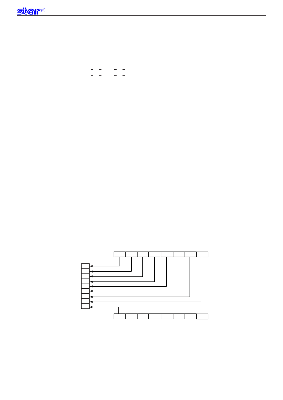
The following drawing shows the relationship of the print head needle wires and the data.
dn: 1 to 8 pin data
dn + 1: 9 pin data
1
●
2
●
3
●
4
●
5
●
6
●
7
●
8
●
9
●
b7
b6
b5
b4
b3
b2
b1
b0
b7
b6
b5
b4
b3
b2
b1
b0
Pin No
MSB
MSB
LSB
LSB
dn + 1 : 9 Pin data