Reference system on milling machines – HEIDENHAIN TNC 410 ISO Programming User Manual
Page 65
HEIDENHAIN TNC 410, TNC 426, TNC 430
39
4.1 F
u
n
d
amen
ta
ls
Reference system on milling machines
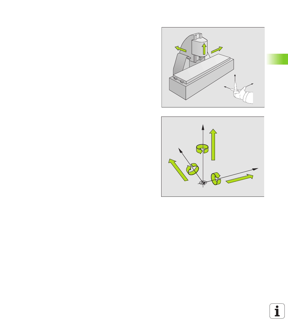
When using a milling machine, you orient tool movements to the
Cartesian coordinate system. The illustration at right shows how the
Cartesian coordinate system describes the machine axes. The figure
at center right illustrates the “right-hand rule” for remembering the
three axis directions: the middle finger is pointing in the positive
direction of the tool axis from the workpiece toward the tool (the Z
axis), the thumb is pointing in the positive X direction, and the index
finger in the positive Y direction.
The TNC 410 can control a maximum of 4 axes, the TNC 426 a
maximum of 5 axes and the TNC 430 a maximum of 9 axes. The axes
U, V and W are secondary linear axes parallel to the main axes X, Y and
Z, respectively. Rotary axes are designated as A, B and C. The
illustration at lower right shows the assignment of secondary axes and
rotary axes to the main axes.
+X
+Y
+Z
+X
+Z
+Y
W+
C+
B+
V+
A+
U+
Y
X
Z