HEIDENHAIN TNC 410 ISO Programming User Manual
Page 162
136
6 Programming: Programming Contours
6.
4 P
a
th Con
to
u
rs—
C
ar
te
sian Co
or
d
inat
e
s
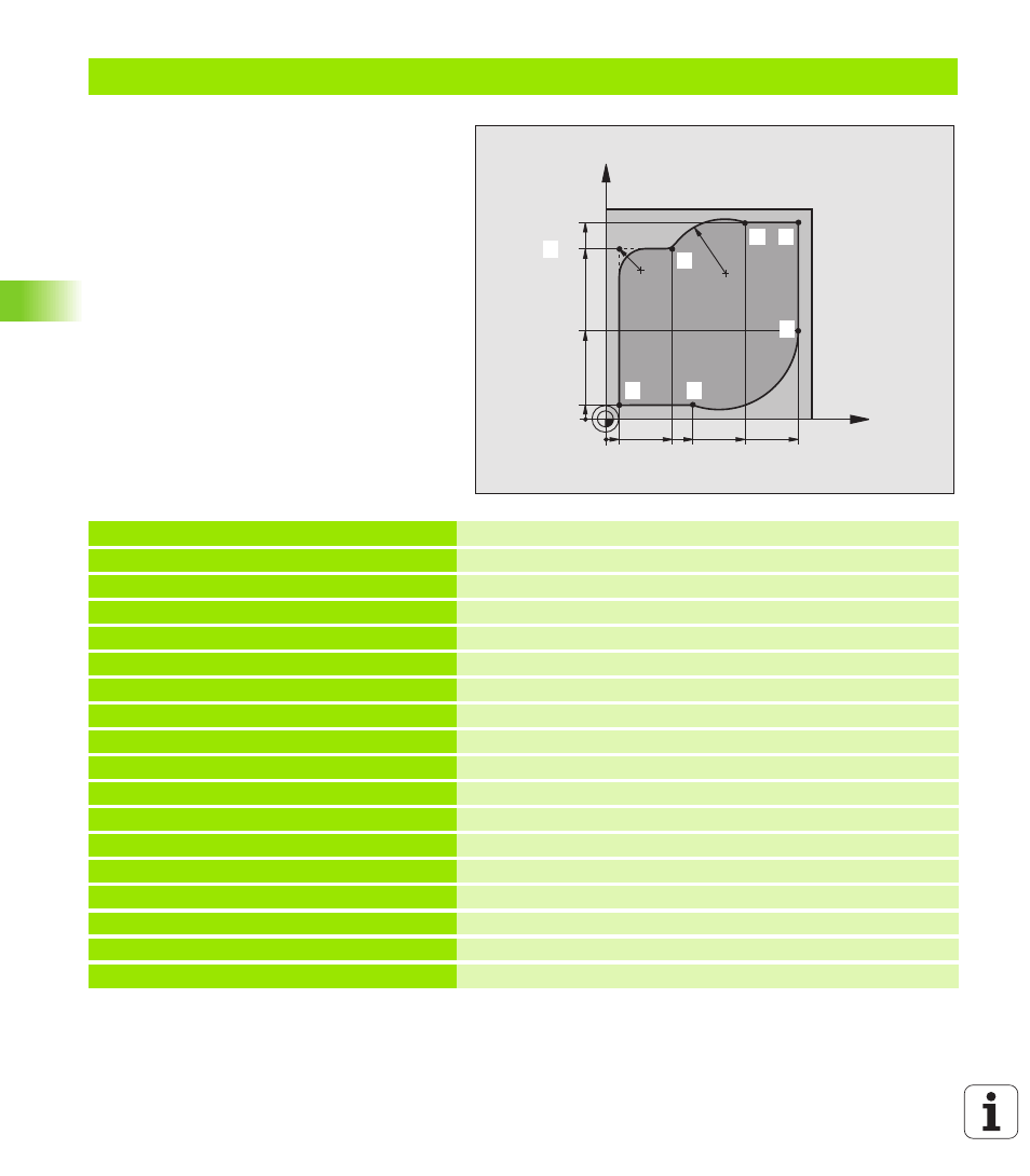
Example: Circular movements with Cartesian coordinates
%CIRCULAR G71 *
N10 G30 G17 X+0 Y+0 Z-20 *
Define blank form for graphic workpiece simulation
N20 G31 G90 X+100 Y+100 Z+0 *
N30 G99 T1 L+0 R+10 *
Define tool in the program
N40 T1 G17 S4000 *
Call tool in the spindle axis and with the spindle speed S
N50 G00 G40 G90 Z+250 *
Retract tool in the spindle axis at rapid traverse
N60 X-10 Y-10 *
Pre-position the tool
N70 G01 Z-5 F1000 M3 *
Move to working depth at feed rate F = 1000 mm/min
N80 G01 G41 X+5 Y+5 F300 *
Approach the contour at point 1, activate radius compensation G41
N90 G26 R5 F150 *
Tangential approach
N100 Y+85 *
Point 2: first straight line for corner 2
N110 G25 R10 *
Insert radius with R = 10 mm, feed rate: 150 mm/min
N120 X+30 *
Move to point 3: Starting point of the arc
N130 G02 X+70 Y+95 R+30 *
Move to point 4: end point of the arc with G02, radius 30 mm
N140 G01 X+95 *
Move to point 5
N150 Y+40 *
Move to point 6
N160 G06 X+40 Y+5 *
Move to point 7: End point of the arc, radius with tangential
connection to point 6, TNC automatically calculates the radius
X
Y
95
5
95
5
85
40
40
30
70
R10
R30
1
1
1
2
1
3
1
4
1
5
1
6
1
7