HEIDENHAIN TNC 410 ISO Programming User Manual
Page 224
198
8 Programming: Cycles
8.3 Cy
cles f
o
r Dr
illing
, T
a
p
p
ing
and
Th
read Millin
g
U
U
U
U
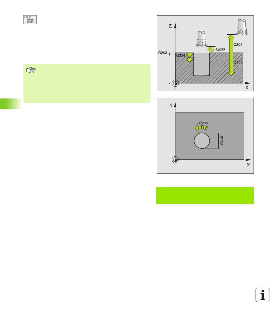
Set-up clearance
Q200 (incremental value): Distance
between tool lower edge and workpiece surface.
U
U
U
U
Depth
Q201 (incremental value): Distance between
workpiece surface and bottom of hole.
U
U
U
U
Feed rate for plunging
Q206: Traversing speed of
the tool during helical drilling in mm/min.
U
U
U
U
Infeed per helix
Q334 (incremental value): Depth of
the tool plunge with each helix (=360°).
U
U
U
U
Workpiece surface coordinate
Q203 (absolute
value): Coordinate of the workpiece surface.
U
U
U
U
2nd set-up clearance
Q204 (incremental value):
Coordinate in the tool axis at which no collision
between tool and workpiece (clamping devices) can
occur.
U
U
U
U
Nominal diameter
Q335 (absolute value): Bore-hole
diameter. If you have entered the nominal diameter to
be the same as the tool diameter, the TNC will bore
directly to the entered depth without any helical
interpolation.
U
U
U
U
Roughing diameter
Q342 (absolute value): As soon as
you enter a value greater than 0 in Q342, the TNC no
longer checks the ratio between the nominal
diameter and the tool diameter. This allows you to
rough-mill holes whose diameter is more than twice
as large as the tool diameter.
Example: NC block
N12 G208 Q200=2 Q201=-80 Q206=150
Q334=1.5 Q203=+100 Q204=50 Q335=25
Q342=0 *
Note that if the infeed distance is too large, the tool or the
workpiece may be damaged.
To prevent the infeeds being too large, enter the max.
plunge angle of the tool in the tool table, column ANGLE,
see “Tool Data,” page 99. The TNC then automatically
calculates the max. infeed permitted and changes your
entered value accordingly.