Tangential approach and departure, 3 con tou r a ppr oa c h and dep a rt ur e – HEIDENHAIN TNC 410 ISO Programming User Manual
Page 150
124
6 Programming: Programming Contours
6
.3 Con
tou
r A
ppr
oa
c
h
and
Dep
a
rt
ur
e
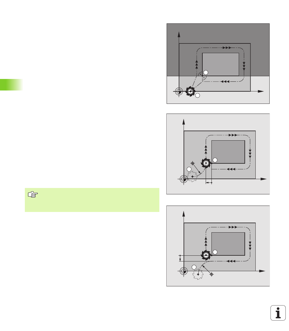
Common starting and end points
Do not program any radius compensation if the starting point and end
point are the same.
In order to make sure the contour will not be damaged, the optimal
starting point should lie between the extended tool paths for
machining the first and last contour elements.
Example
Figure at upper right: If you set the starting point in the dark gray area,
the contour will be damaged when the first contour element is
approached.
Tangential approach and departure
With G26 (figure at center right), you can program a tangential approach
to the workpiece, and with G27 (figure at lower right) a tangential
departure. In this way you can avoid dwell marks.
Starting point and end point
The starting point and the end point lie outside the workpiece, close
to the first and last contour points. They are to be programmed
without radius compensation.
Approach
U
U
U
U
G26
is entered after the block in which the first contour element is
programmed: This will be the first block with radius compensation
G41/G42.
Departure
U
U
U
U
G27
after the block in which the last contour element is
programmed: This will be the last block with radius compensation
G41/G42.
X
Y
A
E
The radius for G26 and G27 must be selected so that the
TNC can execute the circular path between the starting
point and the first contour point, as well as the last contour
point and the end point.
X
Y
A
R
S
G41
G40
X
Y
G41
G40
E
R
B