Grass Valley Trinix Multiviewer Installation User Manual
Page 95
95
TRINIX TMV Installation and Service Manual
Section 5 — System Configuration
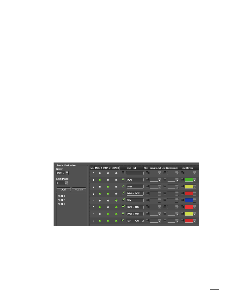
The Router Destination Area
The Router Destination area is where you add destinations and configure
the display rules for this set of destinations. Each row corresponds to a rule
that will be executed when a source matches the row's condition for the
configured destinations. Green LEDs indicates the source and the level are
selected for the destination. Light gray LEDs indicate the source and the
level are not selected for the destination.
In the example shown in
, three destinations have been
selected, MON-1, MON-2, and MON-3 and 2^n combinations of these
three destinations are shown:
•
MON-1 to PGM (program)
•
MON-2 to PVW (preview)
•
MON-3 to AUX (auxiliary)
For example, if the source routed to the associated tile is only routed to
MON-1, then the rule in row 1 will be executed. The text "PGM" will be dis-
played in the Text Box, but the border will use the statically configured
color. If the source routed to the associated tile is routed to both MON-1 and
MON-2 and not MON-3, then the text "PGM + PVW" will be displayed in
the Text Box but the border will use the statically configured color.
Note
Since the Use (Foreground, Background, and Border) check boxes are not
selected, the statically configured colors will be used.
Figure 56. The Router Destination Area
Adding a Router Destination
Follow these steps to add a Router destination:
1.
Select the destination from the
Name
drop down list.