Grass Valley Trinix Multiviewer Installation User Manual
Page 209
209
TRINIX — TMV Installation and Service Manual
Section 10 — TMV Troubleshooting
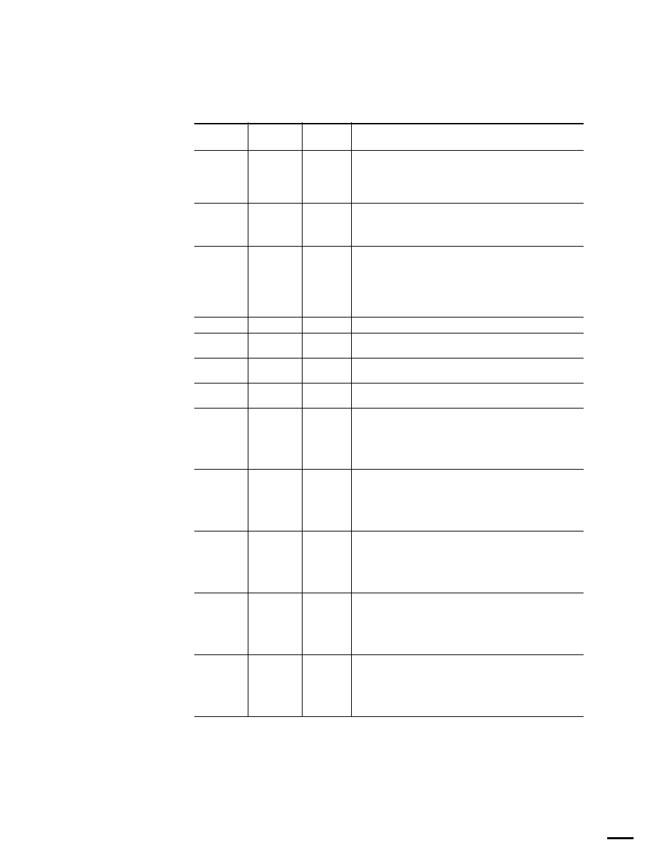
These LEDs are described below in
.
Table 21. TMV LEDs
Shown on
Board
Name
Color
Description
DS11
ETH1
Yellow
Facility LAN – blinks when LAN connected normally.
Note
The TMV board requires LAN connections in order
to boot in a timely fashion
DS9
ETH0
Yellow
Control LAN – blinks when LAN connected normally.
Note
The TMV board requires LAN connections in order
to boot in a timely fashion
DS7
COMM
Yellow
Indicates when the gateware has been loaded.
Note
When starting, the COMM will come on first for a
few seconds, then all the yellow MV’s will light up
rapidly.
DS14
MV3
Yellow
Indicates when the gateware has been loaded.
DS12
MV2
Yellow
Indicates when the gateware has been loaded.
DS6
MV1
Yellow
Indicates when the gateware has been loaded.
DS2
MV0
Yellow
Indicates when the gateware has been loaded.
DS3
CM0
Blue
When the TMV board has booted successfully CM1 is off, CM0 is on,
and 0, 1, 2, 3 blink together, once per second.
The blinking means the corresponding MV FPGA is receiving time
messages from the COMM FPGA. Since all FPGAs receive the same
message, all the blue LEDs should blink together.
DS5
CM1
Blue
When the TMV board has booted successfully CM1 is off, CM0 is on,
and 0, 1, 2, 3 blink together, once per second.
The blinking means the corresponding MV FPGA is receiving time
messages from the COMM FPGA. Since all FPGAs receive the same
message, all the blue LEDs should blink together.
DS4
0
Blue
When the TMV board has booted successfully CM1 is off, CM0 is on,
and 0, 1, 2, 3 blink together, once per second.
The blinking means the corresponding MV FPGA is receiving time
messages from the COMM FPGA. Since all FPGAs receive the same
message, all the blue LEDs should blink together.
DS8
1
Blue
When the TMV board has booted successfully CM1 is off, CM0 is on,
and 0, 1, 2, 3 blink together, once per second.
The blinking means the corresponding MV FPGA is receiving time
messages from the COMM FPGA. Since all FPGAs receive the same
message, all the blue LEDs should blink together.
DS13
2
Blue
When the TMV board has booted successfully CM1 is off, CM0 is on,
and 0, 1, 2, 3 blink together, once per second.
The blinking means the corresponding MV FPGA is receiving time
messages from the COMM FPGA. Since all FPGAs receive the same
message, all the blue LEDs should blink together.