Figure 4-2, Spi device multiplexing logic, Functional description – Artesyn MVME2502 Installation and Use (April 2015) User Manual
Page 96
Functional Description
MVME2502 Installation and Use (6806800R96E)
96
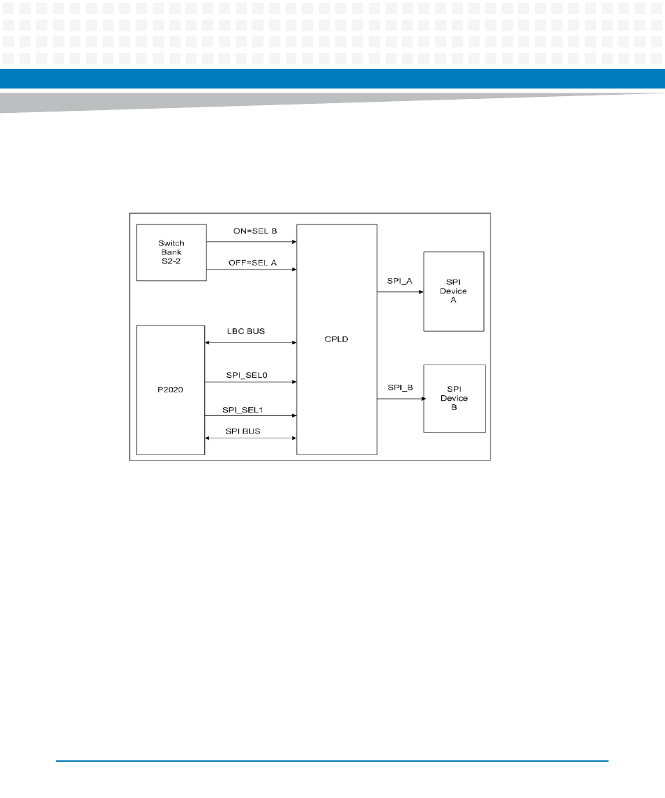
The MVME2502 CPLD controls the chip select to SPI devices A and B. The CPLD chip select
control is based on the Switch Bank (S2-2).
On power-up, the selection of the SPI boot device is strictly based upon the Switch Bank (S2-2)
setting. Depending on the S2-2 setting, SPI_SEL0 is routed to one of two SPI devices. The
selected SPI device must contain a boot image. Once the boot image is copied into memory
and executed, the CPLD will wait, and once the P2020 will write on one bit of the CPLD
watchdog register, the CPLD will then pass through the SPI chip select from the P2020 to SPI
device chip selects. Now the software can perform read/write processes on any SPI device,
including copying from one SPI device to another.
With this flexible approach to firmware redundancy, one should always be able to recover from
a corrupt active firmware image, as long as a healthy firmware image is maintained in single
bootable SPI Device.
The MVME2502 supports automatic switch over. If booting one device is not successful, the
watchdog will trigger the board reset and it will automatically boot on the other device.
Figure 4-2
SPI Device Multiplexing Logic
- MVME2502 Installation and Use (August 2014) MVME2500 Installation and Use Manual (February 2014) MVME2500 ECC Installation and Use (August 2014) MVME2500 Installation and Use (April 2015) MVME2500 Installation and Use Manual (March 2015) MVME2502 Installation and Use (April 2014) MVME2502 Installation and Use (December 2014)