Table 3-12, Pmc j14 connector, Controls, leds, and connectors – Artesyn MVME2502 Installation and Use (April 2015) User Manual
Page 72
Controls, LEDs, and Connectors
MVME2502 Installation and Use (6806800R96E)
72
18
AD 58
50
GND
19
AD 57
51
GND
20
GND
52
AD 36
21
+3.3V
53
AD 35
22
AD 56
54
AD 34
23
AD 55
55
AD 33
24
AD 54
56
GND
25
AD 53
57
+3.3V
26
GND
58
AD 32
27
GND
59
NC
28
GND
60
NC
29
AD 51
61
NC
30
AD 50
62
GND
31
AD 49
63
GND
32
GND
64
NC
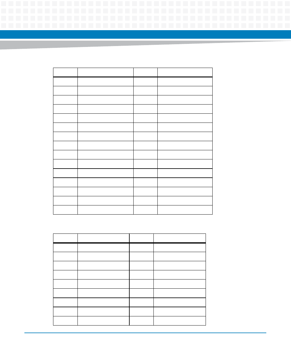
Table 3-12 PMC J14 Connector
Pin
Signal Description
Pin
Signal Description
1
PMC IO 1
33
PMC IO 33
2
PMC IO 2
34
PMC IO 34
3
PMC IO 3
35
PMC IO 35
4
PMC IO 4
36
PMC IO 36
5
PMC IO 5
37
PMC IO 37
6
PMC IO 6
38
PMC IO 38
7
PMC IO 7
39
PMC IO 39
8
PMC IO 8
40
PMC IO 40
9
PMC IO 9
41
PMC IO 41
Table 3-11 PMC J13/J333 Connector (continued)
Pin
Signal Description
Pin
Signal Description
This manual is related to the following products:
- MVME2502 Installation and Use (August 2014) MVME2500 Installation and Use Manual (February 2014) MVME2500 ECC Installation and Use (August 2014) MVME2500 Installation and Use (April 2015) MVME2500 Installation and Use Manual (March 2015) MVME2502 Installation and Use (April 2014) MVME2502 Installation and Use (December 2014)