Controls, leds, and connectors – Artesyn MVME2502 Installation and Use (April 2015) User Manual
Page 69
Controls, LEDs, and Connectors
MVME2502 Installation and Use (6806800R96E)
69
8
+5V
40
LOCK
9
INT D
41
NC
10
NC
42
NC
11
GND
43
PAR
12
NC
44
GND
13
PCI CLK
45
+3.3V
14
GND
46
AD 15
15
GND
47
AD 12
16
GNT A
48
AD 11
17
REQ A
49
AD 9
18
+5V
50
+5V
19
+3.3V
51
GND
20
AD 31
52
CBE0
21
AD 28
53
AD 6
22
AD 27
54
AD 5
23
AD 25
55
AD 4
24
GND
56
GND
25
GND
57
+3.3V
26
CBE3
58
AD 3
27
AD 22
59
AD 2
28
AD 21
60
AD 1
29
AD 19
61
AD 0
30
+5V
62
+5V
31
+3.3V
63
GND
32
AD 17
64
REQ64
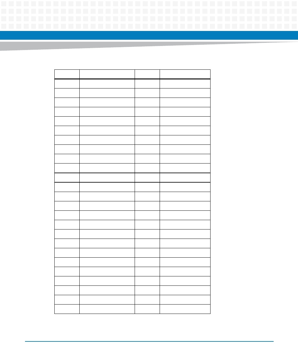
Table 3-9 PMC J11/J111 Connector (continued)
Pin
Signal Description
Pin
Signal Description
This manual is related to the following products:
- MVME2502 Installation and Use (August 2014) MVME2500 Installation and Use Manual (February 2014) MVME2500 ECC Installation and Use (August 2014) MVME2500 Installation and Use (April 2015) MVME2500 Installation and Use Manual (March 2015) MVME2502 Installation and Use (April 2014) MVME2502 Installation and Use (December 2014)