5 xmc connector (xj1), Table 3-15, Xmc connector (xj1) pin out – Artesyn MVME2502 Installation and Use (April 2015) User Manual
Page 76: Controls, leds, and connectors
Controls, LEDs, and Connectors
MVME2502 Installation and Use (6806800R96E)
76
3.4.2.5
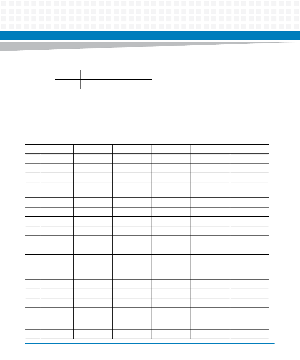
XMC Connector (XJ1)
The MVME2502 supports two XMC sites. The board only support J15 for XMC site 1 and J25 for
XMC site 2.
16
GND
Table 3-14 COP Header (P50) (continued)
Pin
Signal Description
Table 3-15 XMC Connector (XJ1) Pin out
Pin
Row A
Row B
Row C
Row D
Row E
Row F
1
RX0 +
RX0 -
+3.3V
NC
NC
+3.3V
2
GND
GND
JTAG TRST
GND
GND
HRESET
3
NC
NC
+3.3V
NC
NC
+3.3V
4
GND
GND
JTAG TCK
GND
GND
MRSTO
(PULLED UP)
5
NC
NC
+3.3V
NC
NC
+3.3V
6
GND
GND
JTAG TMS
GND
GND
+12V
7
NC
NC
+3.3V
NC
NC
+3.3V
8
GND
GND
JTAG TMS
GND
GND
-12V
9
NC
NC
NC
NC
NC
+3.3V
10
GND
GND
JTAG TDO
GND
GND
GA 0
11
TX0
TX0 -
BIST (PULLED
UP)
NC
NC
+3.3V
12
GND
GND
GA 1
GND
GND
PRESENT
13
NC
NC
NC
NC
NC
+3.3V
14
GND
GND
GA 2
GND
GND
I2C DATA
15
NC
NC
NC
NC
NC
+3.3V
16
GND
GND
MVMRO
(PULLED
DOWN)
GND
GND
I2C CLOCK
17
NC
NC
NC
NC
NC
NC
- MVME2502 Installation and Use (August 2014) MVME2500 Installation and Use Manual (February 2014) MVME2500 ECC Installation and Use (August 2014) MVME2500 Installation and Use (April 2015) MVME2500 Installation and Use Manual (March 2015) MVME2502 Installation and Use (April 2014) MVME2502 Installation and Use (December 2014)