7 pld led control register, Table 5-10, Pld led control register – Artesyn MVME2502 Installation and Use (April 2015) User Manual
Page 117
Memory Maps and Registers
MVME2502 Installation and Use (6806800R96E)
117
5.5.7
PLD LED Control Register
The MVME2502 PLD provides an 8-bit register which controls the eight LEDs.
1 - LED on
0 - LED off
RESET
0
0
0
0
0
0
0
0
Field Description
PWR_V1P05_PWRGD
1.05V Core supply power good indicator
PWR_V1P2_PWRGD
1.2V Supply power good indicator
PWR_V1P8_PWRGD
1.8V Supply power good indicator
PWR_V3P3_PWRGD
3.3V Supply power good indicator
PWR_V2P5_PWRGD
2.5V Supply power good indicator
PWR_V1P2_SW_PWRG
D
1.2V SW Supply power good indicator
PWR_V1P5_PWRGD
1.5V Supply power good indicator
1 - Supply Good and Stable
0 - Otherwise
Table 5-9 PLD Power Good Monitor Register (continued)
REG
PLD PWRDG_MNTR - 0xFFDF0012
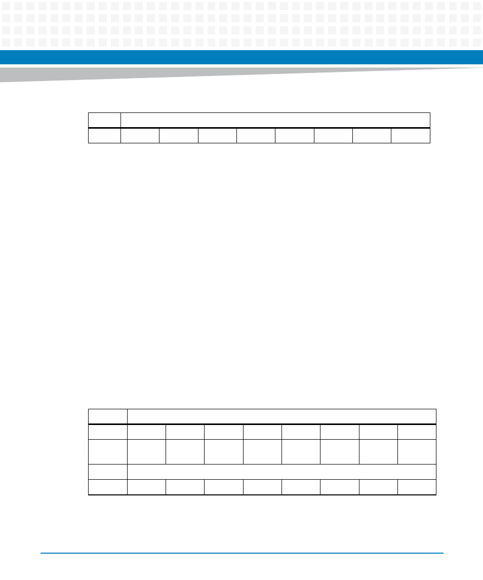
Table 5-10 PLD LED Control Register
REG
PLD LED_CTRL - 0xFFDF001C
Bit
7
6
5
4
3
2
1
0
Field
D1
D35
D34
D33
D38
D37
D2 Red
D2
Yellow
OPER
R/W
RESET
1
0
0
0
0
0
0
0
- MVME2502 Installation and Use (August 2014) MVME2500 Installation and Use Manual (February 2014) MVME2500 ECC Installation and Use (August 2014) MVME2500 Installation and Use (April 2015) MVME2500 Installation and Use Manual (March 2015) MVME2502 Installation and Use (April 2014) MVME2502 Installation and Use (December 2014)