Controls, leds, and connectors – Artesyn MVME2502 Installation and Use (April 2015) User Manual
Page 65
Controls, LEDs, and Connectors
MVME2502 Installation and Use (6806800R96E)
65
17
GND
AM 1
ADD 25
GA4
NC
18
AS
AM 2
ADD 26
+3.3V (not
used)
GND
19
GND
AM 3
ADD 27
NC
NC
20
IACK
GND
ADD 28
+3.3V (not
used)
GND
21
IACKIN
NC
ADD 29
NC
NC
22
IACKOUT
NC
ADD 30
+3.3V (not
used)
GND
23
AM 4
GND
ADD 31
NC
NC
24
ADD 7
IRQ7
ADD 32
+3.3V (not
used)
GND
25
ADD 6
IRQ6
ADD 33
NC
NC
26
ADD 5
IRQ5
ADD 34
+3.3V (not
used)
GND
27
ADD 4
IRQ4
ADD 35
NC
NC
28
ADD 3
IRQ3
ADD 36
+3.3V (not
used)
GND
29
ADD 2
IRQ2
ADD 37
NC
NC
30
ADD 1
IRQ1
ADD 38
+3.3V (not
used)
GND
31
-12V
NC
+12V
+12V
NC
32
+5V
+5V
+5V
+5V
GND
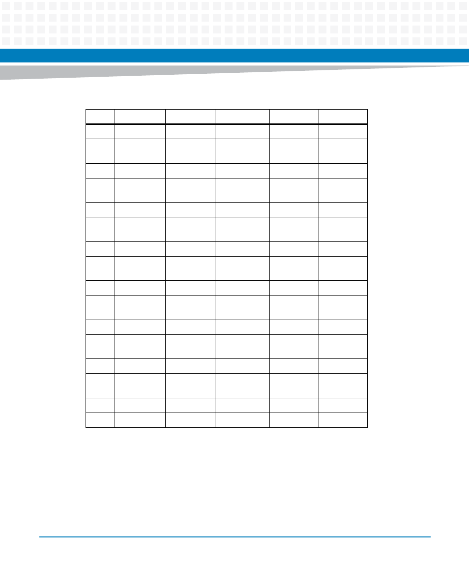
Table 3-6 VMEbus P1 Connector (continued)
Pin
Row A
Row B
Row C
Row D
Row Z
This manual is related to the following products:
- MVME2502 Installation and Use (August 2014) MVME2500 Installation and Use Manual (February 2014) MVME2500 ECC Installation and Use (August 2014) MVME2500 Installation and Use (April 2015) MVME2500 Installation and Use Manual (March 2015) MVME2502 Installation and Use (April 2014) MVME2502 Installation and Use (December 2014)