2 pmc connectors, Table 3-9, Pmc j11/j111 connector – Artesyn MVME2502 Installation and Use (April 2015) User Manual
Page 68: Controls, leds, and connectors
Controls, LEDs, and Connectors
MVME2502 Installation and Use (6806800R96E)
68
3.4.2.2
PMC Connectors
The MVME2502 supports two PMC sites. It utilizes J14 to support PMC I/O that goes to the RTM
PMC. The tables below show the pin out detail of J11/J111, J12/J222, J13/J333 and J14. See
for the location of the PMC connectors.
9
GND
29
GND
10
GND
30
GND
11
NC
31
+3.3V
12
SATA RX -
32
+5V
13
NC
33
+3.3V
14
SATA RX +
34
+5V
15
GND
35
+3.3V
16
GND
36
+5V
17
NC
37
+3.3V
18
GND
38
+5V
19
NC
39
+3.3V
20
GND
40
+5V
Table 3-8 Custom SATA Connector (J3) (continued)
Pin
Signal Description
Pin
Signal Description
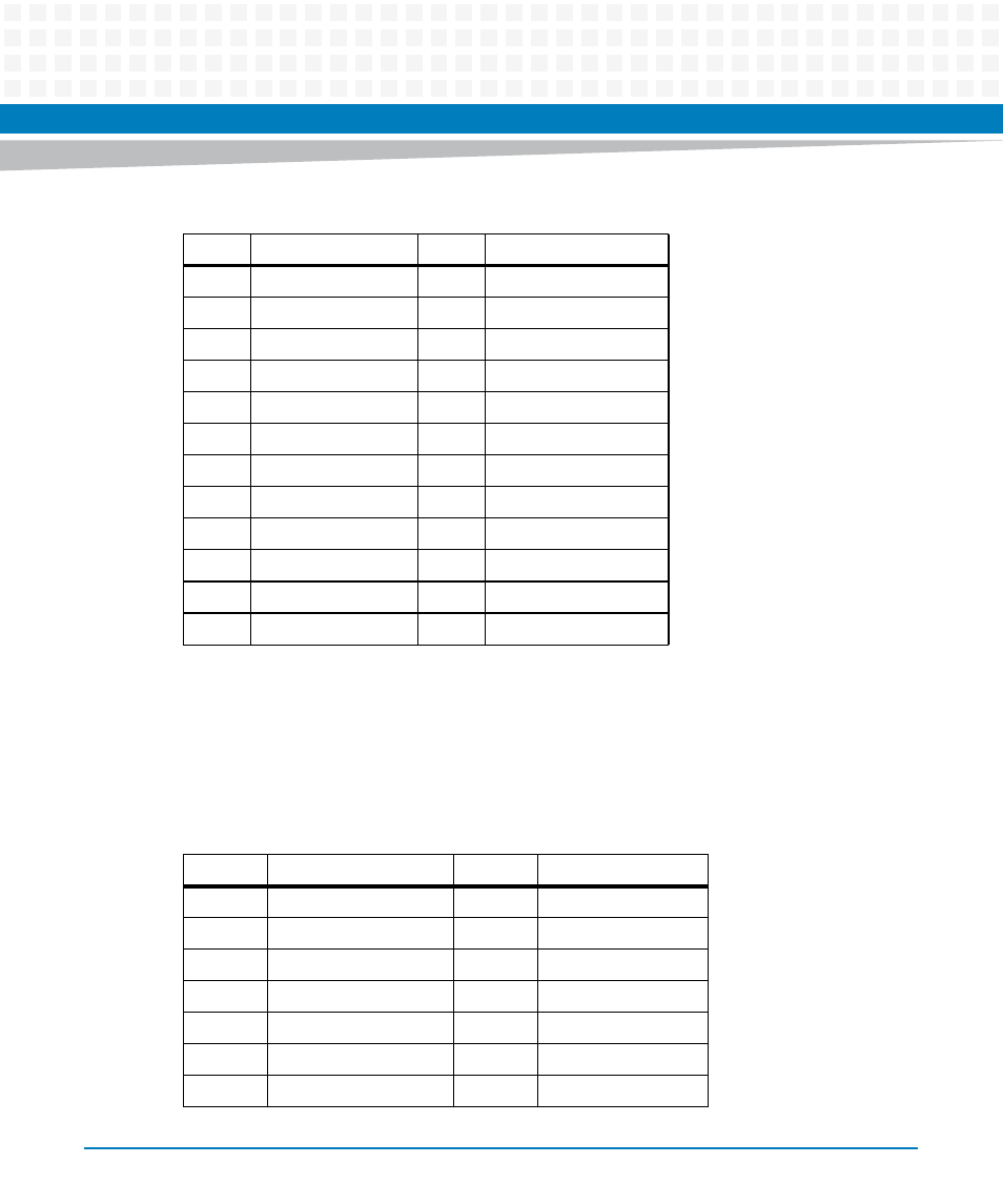
Table 3-9 PMC J11/J111 Connector
Pin
Signal Description
Pin
Signal Description
1
JTAG TCK
33
FRAME
2
-12V
34
GND
3
GND
35
GND
4
INT A
36
IRDY
5
INT B
37
DEVSEL
6
INT C
38
+5V
7
PRESENT SIGNAL
39
PCIXCAP
This manual is related to the following products:
- MVME2502 Installation and Use (August 2014) MVME2500 Installation and Use Manual (February 2014) MVME2500 ECC Installation and Use (August 2014) MVME2500 Installation and Use (April 2015) MVME2500 Installation and Use Manual (March 2015) MVME2502 Installation and Use (April 2014) MVME2502 Installation and Use (December 2014)