2 on-board connectors, 1 sata connector (j3), Table 3-8 – Artesyn MVME2502 Installation and Use (April 2015) User Manual
Page 67: Custom sata connector (j3), Controls, leds, and connectors
Controls, LEDs, and Connectors
MVME2502 Installation and Use (6806800R96E)
67
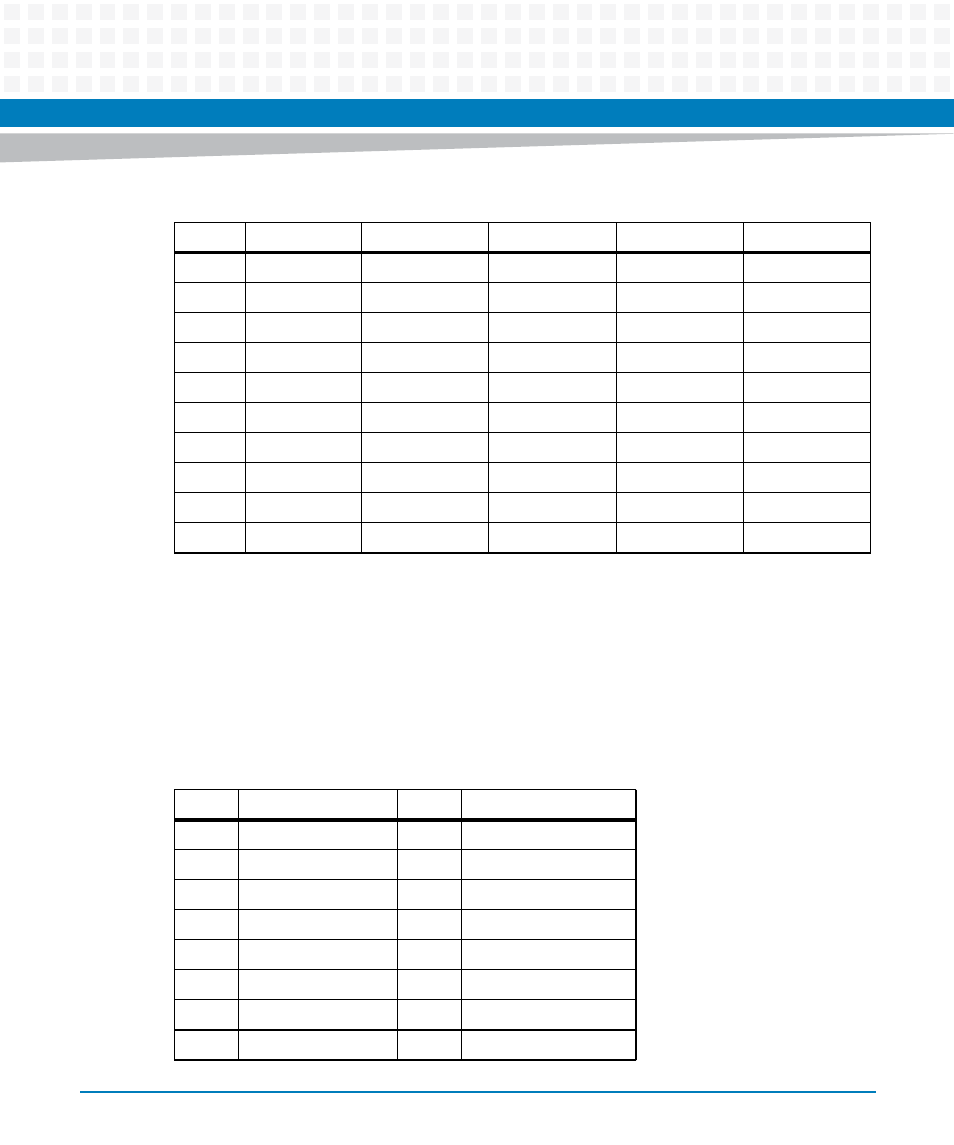
3.4.2
On-board Connectors
3.4.2.1
SATA Connector (J3)
The on-board customized SATA connector is compatible with SATA kit, namely VME-
64GBSSDKIT and IVME7210-MNTKIT.
23
PMC IO 46
DATA 24
PMC IO 45
GE4_2 -
Serial 3 RTS
24
PMC IO 48
DATA 25
PMC IO 47
GE4_2+
GND
25
PMC IO 50
DATA 26
PMC IO 49
GND
Serial 4 RX
26
PMC IO 52
DATA 27
PMC IO 51
GE4_1 -
GND
27
PMC IO 54
DATA 28
PMC IO 53
GE4_1 +
Serial 4 TX
28
PMC IO 56
DATA 29
PMC IO 55
GND
GND
29
PMC IO 58
DATA 30
PMC IO 57
GE4_0 -
Serial 4 CTS
30
PMC IO 60
DATA 31
PMC IO 59
GE4_0 +
GND
31
PMC IO 62
GND
PMC IO 61
GND
Serial 4 RTS
32
PMC IO 64
+5V
PMC IO 63
+5V
GND
Table 3-7 VMEbus P2 Connector (continued)
Pin
Row A
Row B
Row C
Row D
Row Z
Table 3-8 Custom SATA Connector (J3)
Pin
Signal Description
Pin
Signal Description
1
GND
21
GND
2
GND
22
SATA POWER ENABLE
3
NC
23
NC
4
SATA TX +
24
SATA DETECT
5
NC
25
NC
6
SATA TX -
26
GND
7
GND
27
NC
8
GND
28
GND
- MVME2502 Installation and Use (August 2014) MVME2500 Installation and Use Manual (February 2014) MVME2500 ECC Installation and Use (August 2014) MVME2500 Installation and Use (April 2015) MVME2500 Installation and Use Manual (March 2015) MVME2502 Installation and Use (April 2014) MVME2502 Installation and Use (December 2014)