2 smt configuration switch (s2), Table 3-19, Geographical address switch settings – Artesyn MVME2502 Installation and Use (April 2015) User Manual
Page 81: Figure 3-7, Smt configuration switch position, Controls, leds, and connectors
Controls, LEDs, and Connectors
MVME2502 Installation and Use (6806800R96E)
81
3.5.2
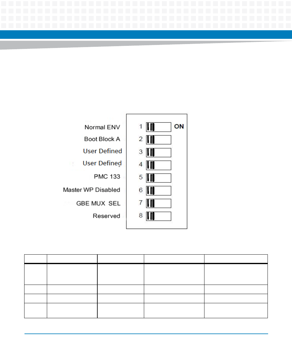
SMT Configuration Switch (S2)
This eight position SMT configuration switch controls the flash bank user defined switch,
selects the flash boot image, and controls the safe start ENV settings. The default setting on all
switch positions is "OFF" and is indicated by brackets in
Figure 3-7
SMT Configuration Switch Position
Table 3-19 Geographical Address Switch Settings
SW2
DEFAULT
Signal Name
Description
Notes
1
OFF (Normal Env)
NORMAL_ENV
Safe Start ("ON"= Use
normal ENV, "OFF"= Use
safe ENV)
2
OFF (Flash Block A)
BOOT_BLOCK_A
Boot Block B Select
3
OFF (WP disabled)
FLASH_WP_N
Flash Write Protect
4
OFF (Auto)
PMC_XMC_SEL
XMC/PMC - Manual Detect
or Auto Detect
Will select if XMC card or
PMC card is used
- MVME2502 Installation and Use (August 2014) MVME2500 Installation and Use Manual (February 2014) MVME2500 ECC Installation and Use (August 2014) MVME2500 Installation and Use (April 2015) MVME2500 Installation and Use Manual (March 2015) MVME2502 Installation and Use (April 2014) MVME2502 Installation and Use (December 2014)