2 power requirements, Table 2-2, Power requirements – Artesyn MVME2502 Installation and Use (April 2015) User Manual
Page 42: Hardware preparation and installation
Hardware Preparation and Installation
MVME2502 Installation and Use (6806800R96E)
42
2.3.2
Power Requirements
The board uses +5.0 V from the VMEbus backplane. On-board power supply generates
required voltages for various ICs. The MVME2502 connects the +12 V and -12 V supplies from
the backplane to the PMC sites, while the +3.3 V power supplied to the PMC sites comes from
the +5.0 V backplane power. A maximum of 10 A of +3.3 V power is available to the PMC sites,
however the 90 W +5.0 V limit must be observed as well as any cooling limitations.
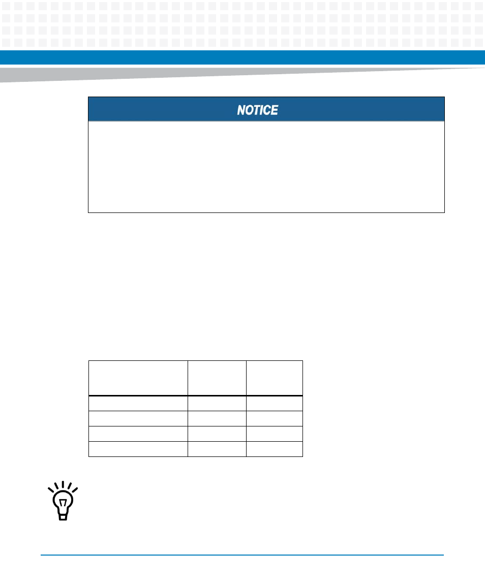
The following table provides an estimate of the typical and maximum power required.
Product Damage
High humidity and condensation on the board surface causes short circuits.
Do not operate the board outside the specified environmental limits.
Make sure that the board is completely dry and there is no moisture on any surface
before applying power.
Table 2-2 Power Requirements
Board Variant
Maximum
(Calculated)
Typical
(Measured
Operating)
MVME2502-02120201E
28.93W
21.8
MVME2502-02120201S
28.93W
21.8
MVME2502-02100202E
23.33W
16.6
MVME2502-02100202S
23.33W
16.6
The power is measured when the board is in standby (Linux prompt) mode. Power will
significantly increase when adding hard drives or a XMC/PMC card.
- MVME2502 Installation and Use (August 2014) MVME2500 Installation and Use Manual (February 2014) MVME2500 ECC Installation and Use (August 2014) MVME2500 Installation and Use (April 2015) MVME2500 Installation and Use Manual (March 2015) MVME2502 Installation and Use (April 2014) MVME2502 Installation and Use (December 2014)