17 reset structure, 1 reset sequence, 18 thermal management – Artesyn MVME2502 Installation and Use (April 2015) User Manual
Page 105: Table 4-6, Thermal interrupt threshold, Functional description
Functional Description
MVME2502 Installation and Use (6806800R96E)
105
4.17 Reset Structure
The MVME2502 reset will initiate after the power up sequence if the 1.5 V power supply is
"GOOD". When the board is at “ready” state, the reset logic will monitor the reset sources and
implement the necessary reset function.
4.17.1 Reset Sequence
The timing of the reset sequence supports each chip reset requirements with respect to the
power supply.
4.18 Thermal Management
The MVME2502 utilizes two on-board temperature sensors: one for the board and the other for
the CPU temperature sensor. The board temperature sensor is located near the processor. The
CPU temperature sensor is located on the processor.
The MVME2502 thermal management support will interrupt the process only to show the
current board and CPU temperature. This interrupt is routed directly to one of the processor’s
IRQ4.
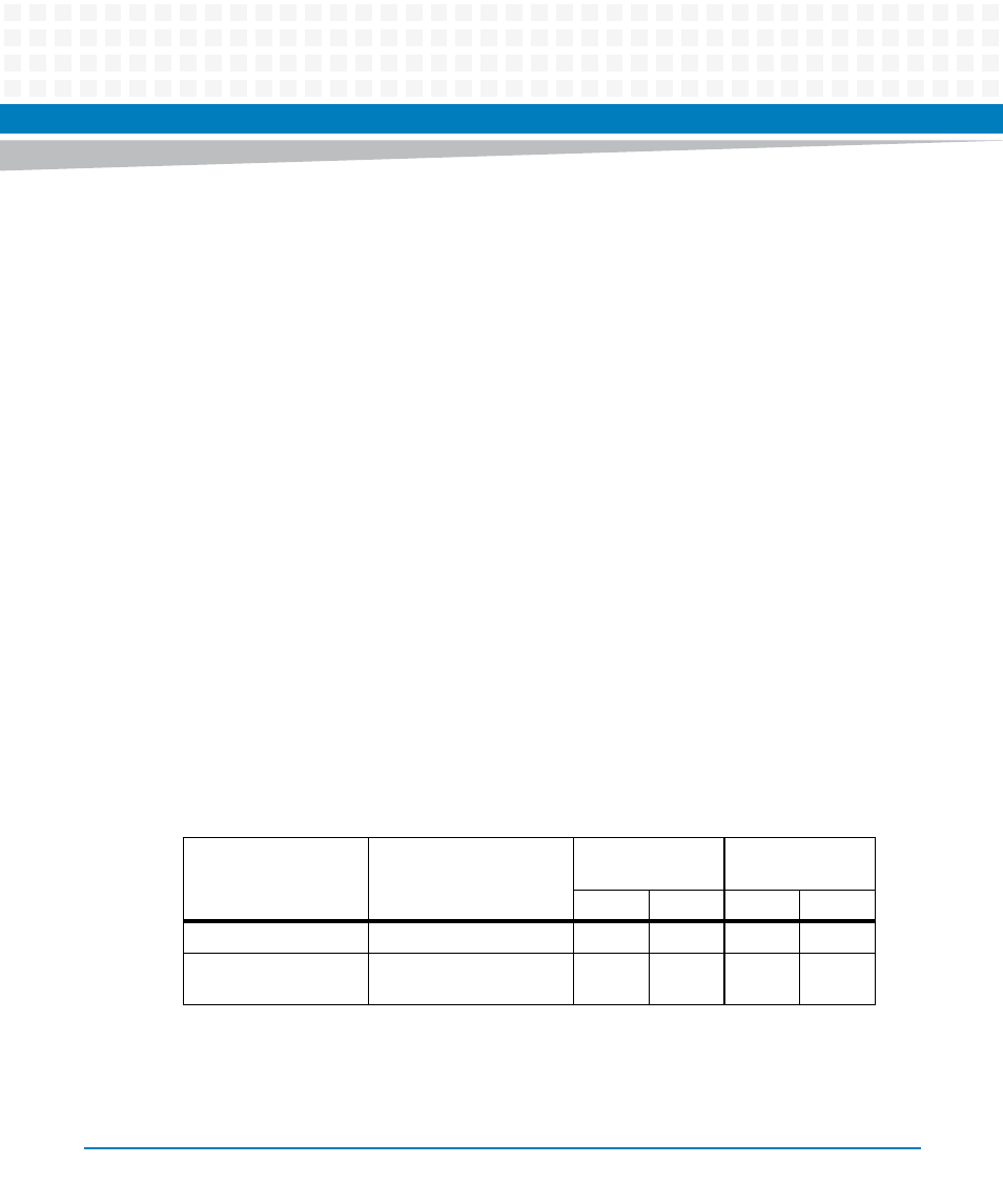
The table below shows the low and high threshold temperature in order for the interrupt to be
asserted.
Table 4-6 Thermal Interrupt Threshold
Board Variant
Board Temperature Limit
Board
Temperature Limit
CPU Temperature
Limit
Low
High
Low
High
Standard Variant
0°C to +55°C
0°C
70°C
0°C
90°C
Extended Temperature
Variant
-40°C to +71°C
-40°C
90°C
-40°C
100°C
- MVME2502 Installation and Use (August 2014) MVME2500 Installation and Use Manual (February 2014) MVME2500 ECC Installation and Use (August 2014) MVME2500 Installation and Use (April 2015) MVME2500 Installation and Use Manual (March 2015) MVME2502 Installation and Use (April 2014) MVME2502 Installation and Use (December 2014)