Controls, leds, and connectors – Artesyn MVME2502 Installation and Use (April 2015) User Manual
Page 62
Controls, LEDs, and Connectors
MVME2502 Installation and Use (6806800R96E)
62
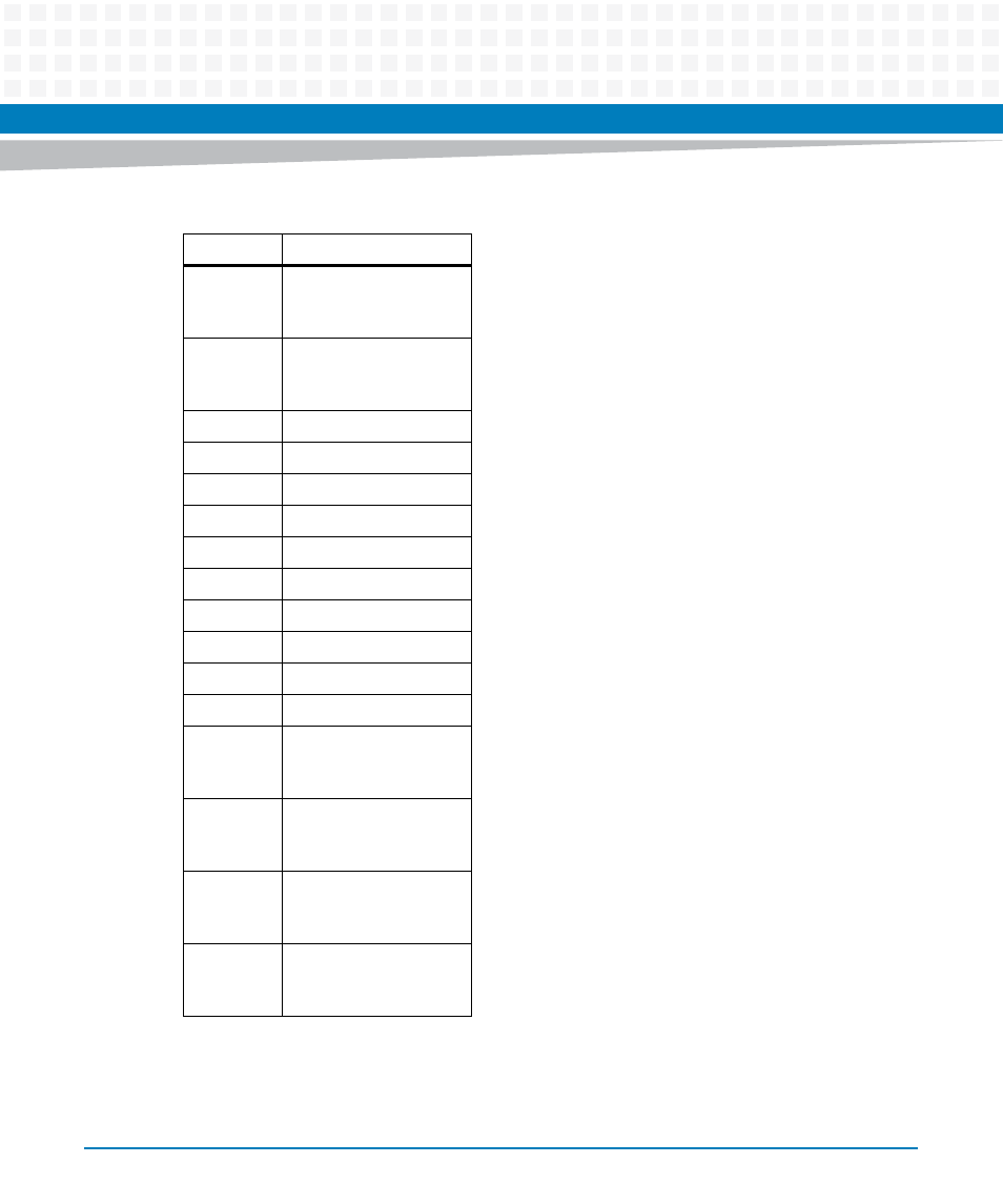
D3A
Port A Green LED2
Anode/ Yellow LED2
Cathode
D4A
Port A Yellow LED2
Anode/ Green LED2
Cathode
1B
GND
2B
NC
3B
Port B TRD3 -
4B
Port B TRD3 +
5B
Port B TRD2 -
6B
Port B TRD2 +
7B
Port B TRD1 -
8B
Port B TRD1 +
9B
Port B TRD0 -
10B
Port B TRD0 +
D1B
Port B Green
LED1Anode/ Yellow
LED1 Cathode
D2B
Port B Yellow LED1
Anode/ Green LED1
Cathode
D3B
Port B Green
LED2Anode/ Yellow
LED2 Cathode
D4B
Port B Yellow LED2
Anode/ Green LED2
Cathode
Table 3-3 Front Panel Tri-Speed Ethernet Connector (J1) (continued)
Pin Name
Signal Description
This manual is related to the following products:
- MVME2502 Installation and Use (August 2014) MVME2500 Installation and Use Manual (February 2014) MVME2500 ECC Installation and Use (August 2014) MVME2500 Installation and Use (April 2015) MVME2500 Installation and Use Manual (March 2015) MVME2502 Installation and Use (April 2014) MVME2502 Installation and Use (December 2014)