3 jtag connector (p6), Table 3-13, Jtag connector (p6) – Artesyn MVME2502 Installation and Use (April 2015) User Manual
Page 74: Controls, leds, and connectors
Controls, LEDs, and Connectors
MVME2502 Installation and Use (6806800R96E)
74
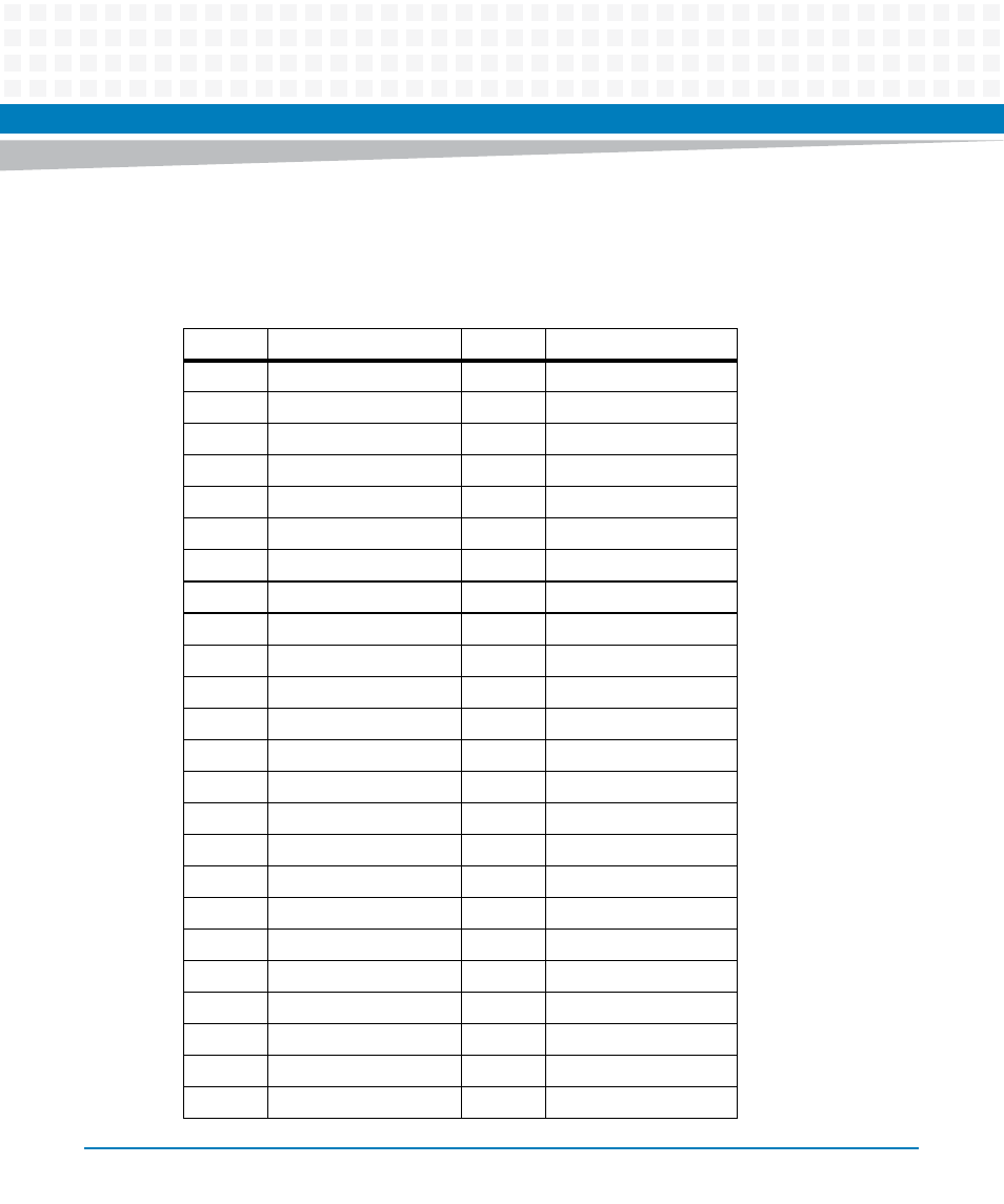
3.4.2.3
JTAG Connector (P6)
The JTAG Connector can be used in conjunction with the JTAG board and ASSET hardware.
Table 3-13 JTAG Connector (P6)
Pin
Signal Description
Pin
Signal Description
1
NC
2
+3.3V FROM +5V
3
SPI HOLD 0
4
SPI CS 0
5
SPI CLK
6
SPI CS 1
7
SPI HOLD 1
8
SPI MOSI
9
SPI MISO
10
GND
11
SPI VCC
12
SCAN 1 TCK
13
SCAN 1 TDI
14
GND
15
SCAN 1 TRST
16
SCAN 1 TDO
17
SCAN 1 TMS
18
+3.3V
19
GPO0
20
NC
21
NC
22
SCAN 2 TMS
23
NC
24
SCAN 2 TDO
25
SCAN 2 TCK
26
+3.3V FROM +5V
27
GND
28
SCAN 2 TDI
29
NC
30
NC
31
SCAN 3 TMS
32
SCAN 3 TCK1
33
SCAN 3 TDO
34
SCAN 3 TCK 2
35
+2.5V
36
SCAN 3 TCK 3
37
SCAN 3 TDI
38
GND
39
SCAN 3 TRST
40
SCAN 3 TCK3
41
SCAN 4 TCK 1
42
SCAN 4 TMS
43
GND
44
SCAN 4 TDO
45
SCAN 4 TCK 2
46
+3.3V
47
GND
48
SCAN 4 TDI
This manual is related to the following products:
- MVME2502 Installation and Use (August 2014) MVME2500 Installation and Use Manual (February 2014) MVME2500 ECC Installation and Use (August 2014) MVME2500 Installation and Use (April 2015) MVME2500 Installation and Use Manual (March 2015) MVME2502 Installation and Use (April 2014) MVME2502 Installation and Use (December 2014)