14 pld test register 2, 15 pld gpio2 interrupt register, Table 5-17 – Artesyn MVME2502 Installation and Use (April 2015) User Manual
Page 125: Pld test register 2, Table 5-18, Pld gpio2 interrupt register
Memory Maps and Registers
MVME2502 Installation and Use (6806800R96E)
125
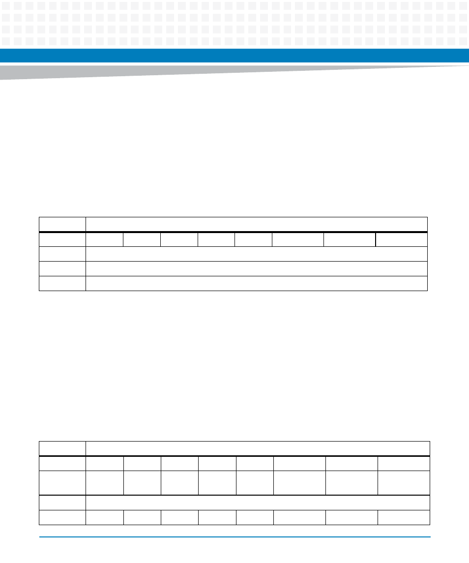
5.5.14 PLD Test Register 2
The MVME2502 PLD provides an 8-bit general purpose read/write register which is used by the
software for PLD testing or general status bit storage.
5.5.15 PLD GPIO2 Interrupt Register
The abort switch, Tick Timer 0, 1 and 2 interrupts are ORed together. The MVME2502 provides
an interrupt register that the system software reads to determine which device the interrupt
originated from. GPIO2 will be driven "low" if any of the interrupts asserts.
Field Description
TEST_REG1
General purpose 8-bit R/W field
Table 5-17 PLD Test Register 2
REG
PLD Write Protect I2C Debug- 0xFFDF0095
Bit
7
6
5
4
3
2
1
0
Field
TEST_REG1
OPER
R/W
RESET
00
Field Description
TEST_REG2
General purpose 8-bit R/W field
Table 5-18 PLD GPIO2 Interrupt Register
REG
PLD Write Protect I2C Debug- 0xFFDF0095
Bit
7
6
5
4
3
2
1
0
Field
CPU_RT
C_SEL
SW2-3
RSVD
RSVD
NMI
TICK0_INT
TICK1_INT
TICK2_INT
OPER
R
RESET
0
0
X
0
0
0
0
0
- MVME2502 Installation and Use (August 2014) MVME2500 Installation and Use Manual (February 2014) MVME2500 ECC Installation and Use (August 2014) MVME2500 Installation and Use (April 2015) MVME2500 Installation and Use Manual (March 2015) MVME2502 Installation and Use (April 2014) MVME2502 Installation and Use (December 2014)