6 xmc connector (xj2), Table 3-16, Xmc connector (xj2) pin out – Artesyn MVME2502 Installation and Use (April 2015) User Manual
Page 77: Controls, leds, and connectors
Controls, LEDs, and Connectors
MVME2502 Installation and Use (6806800R96E)
77
3.4.2.6
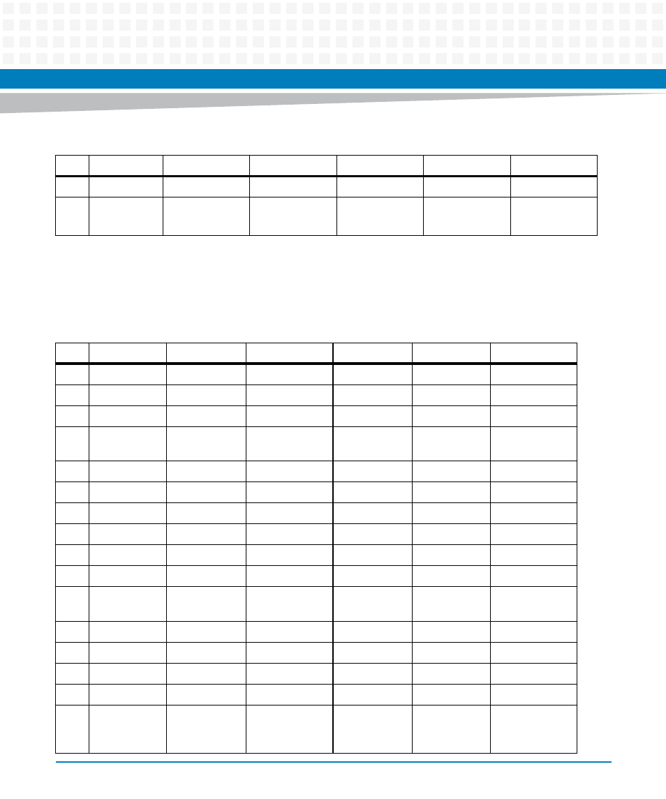
XMC Connector (XJ2)
18
GND
GND
NC
GND
GND
NC
19
CLK +
CLK -
NC
ROOT 0
(PULLED UP)
ROOT0
(PULLED UP)
NC
Table 3-15 XMC Connector (XJ1) Pin out (continued)
Pin
Row A
Row B
Row C
Row D
Row E
Row F
Table 3-16 XMC Connector (XJ2) Pin out
Pin
Row A
Row B
Row C
Row D
Row E
Row F
1
RX0 +
RX0 -
+3.3V
RX1+
RX1-
+3.3V
2
GND
GND
JTAG TRST
GND
GND
HRESET
3
NC
NC
+3.3V
NC
NC
+3.3V
4
GND
GND
JTAG TCK
GND
GND
MRSTO
(PULLED UP)
5
NC
NC
+3.3V
NC
NC
+3.3V
6
GND
GND
JTAG TMS
GND
GND
+12V
7
NC
NC
+3.3V
NC
NC
+3.3V
8
GND
GND
JTAG TMS
GND
GND
-12V
9
NC
NC
NC
NC
NC
+3.3V
10
GND
GND
JTAG TDO
GND
GND
GA 0
11
TX0
TX0 -
BIST (PULLED
UP)
TX1+
TX1-
+3.3V
12
GND
GND
GA 1
GND
GND
PRESENT
13
NC
NC
NC
NC
NC
+3.3V
14
GND
GND
GA 2
GND
GND
I2C DATA
15
NC
NC
NC
NC
NC
+3.3V
16
GND
GND
MVMRO
(PULLED
DOWN)
GND
GND
I2C CLOCK
This manual is related to the following products:
- MVME2502 Installation and Use (August 2014) MVME2500 Installation and Use Manual (February 2014) MVME2500 ECC Installation and Use (August 2014) MVME2500 Installation and Use (April 2015) MVME2500 Installation and Use Manual (March 2015) MVME2502 Installation and Use (April 2014) MVME2502 Installation and Use (December 2014)