Table 3-1, Front panel leds, Controls, leds, and connectors – Artesyn MVME2502 Installation and Use (April 2015) User Manual
Page 59
Controls, LEDs, and Connectors
MVME2502 Installation and Use (6806800R96E)
59
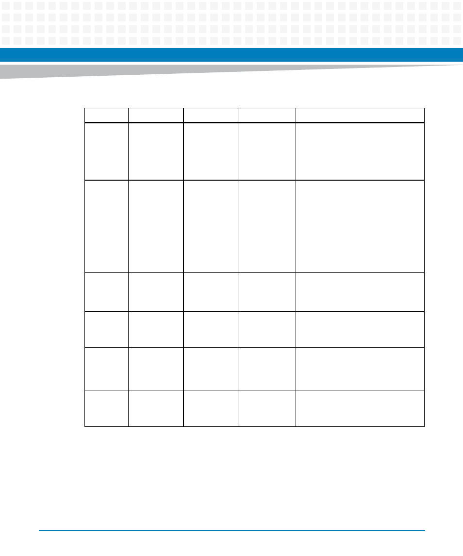
Table 3-1 Front Panel LEDs
Label
Function
Location
Color
Description
USER 1
User Defined
Front panel
Off
Yellow
Red
By default
User Software Controllable. Refer to
the "User LED Register."
User Software Controllable. Refer to
the "User LED Register."
FAIL
Board Fail
Front panel
Off
Red
Normal operation after successful
firmware boot.
One or more on-board power rails
has failed and the board has
shutdown to protect the hardware.
Normal during power up, during
hardware reset (such as a front panel
reset). May be asserted by the BDFAIL
bit in the Tsi148 VSTAT register.
GENET1
SPEED
TSEC1
Link/Speed
Front panel
Integrated
RJ45 LED
Off
Amber
Green
No link
10/100BASE-T operation
1000 BASE-T operation
GENET1
ACT
TSEC1
Activity
Front panel
Integrated
RJ45 LED
Off
Blinking Green
No activity
Activity proportional to bandwidth
utilization
GENET2
SPEED
TSEC2
Link/Speed
Front panel
Integrated
RJ45 LED
(Left)
Off
Amber
Green
No link
10/100BASE-T operation
1000BASE-T operation
GENET2
ACT
TSEC2
Activity
Front panel
Integrated
RJ45 LED
Off
Blinking Green
No activity
Activity proportional to bandwidth
utilization
- MVME2502 Installation and Use (August 2014) MVME2500 Installation and Use Manual (February 2014) MVME2500 ECC Installation and Use (August 2014) MVME2500 Installation and Use (April 2015) MVME2500 Installation and Use Manual (March 2015) MVME2502 Installation and Use (April 2014) MVME2502 Installation and Use (December 2014)