Table 3-11, Pmc j13/j333 connector, Controls, leds, and connectors – Artesyn MVME2502 Installation and Use (April 2015) User Manual
Page 71
Controls, LEDs, and Connectors
MVME2502 Installation and Use (6806800R96E)
71
26
AD 23
58
EREADY
27
+3.3V
59
GND
28
AD 28
60
RSTOUT
29
AD 18
61
ACK64
30
GND
62
+3.3V
31
AD 16
63
GND
32
CBE2
64
NC
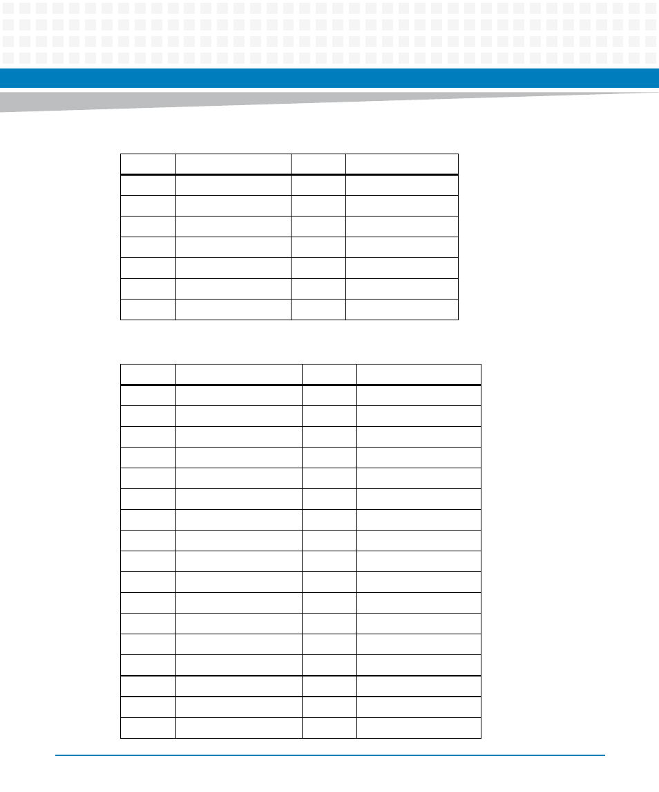
Table 3-11 PMC J13/J333 Connector
Pin
Signal Description
Pin
Signal Description
1
NC
33
GND
2
GND
34
AD48
3
GND
35
AD 47
4
CBE7
36
AD 52
5
CBE6
37
AD 45
6
CBE5
38
GND
7
CBE4
39
+3.3V
8
GND
40
AD 40
9
+3.3V
41
AD 43
10
PAR64
42
AD 42
11
+3.3V
43
AD 41
12
AD 62
44
GND
13
AD 61
45
GND
14
GND
46
AD 40
15
GND
47
AD 39
16
AD 60
48
AD 38
17
AD 59
49
AD 37
Table 3-10 PMC J12/J222 Connector (continued)
Pin
Signal Description
Pin
Signal Description
This manual is related to the following products:
- MVME2502 Installation and Use (August 2014) MVME2500 Installation and Use Manual (February 2014) MVME2500 ECC Installation and Use (August 2014) MVME2500 Installation and Use (April 2015) MVME2500 Installation and Use Manual (March 2015) MVME2502 Installation and Use (April 2014) MVME2502 Installation and Use (December 2014)