4 connectors, 1 front panel connectors, 1 rj45 with integrated magnetics (j1) – Artesyn MVME2502 Installation and Use (April 2015) User Manual
Page 61: Table 3-3, Front panel tri-speed ethernet connector (j1), Controls, leds, and connectors
Controls, LEDs, and Connectors
MVME2502 Installation and Use (6806800R96E)
61
3.4
Connectors
This section describes the pin assignments and signals for the connectors on the MVME2502
board.
3.4.1
Front Panel Connectors
The following connectors are found on the outside of the MVME2502 board. These connectors
are divided between the front panel connectors and the backplane connectors. The front panel
connectors include the J1 and the J5 connectors. The backplane connectors include the P1 and
the P2 connectors.
3.4.1.1
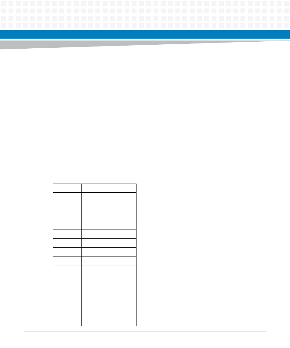
RJ45 with Integrated Magnetics (J1)
The MVME2502 uses an X2 RJ45.
Table 3-3 Front Panel Tri-Speed Ethernet Connector (J1)
Pin Name
Signal Description
1A
GND
2A
NC
3A
Port A TRD3 -
4A
Port A TRD3 +
5A
Port A TRD2 -
6A
Port A TRD2 +
7A
Port A TRD1 -
8A
Port A TRD1 +
9A
Port A TRD0 -
10A
Port A TRD0 +
D1A
Port A Green LED1
Anode/ Yellow LED1
Cathode
D2A
Port A Yellow LED1
Anode/ Green LED1
Cathode
- MVME2502 Installation and Use (August 2014) MVME2500 Installation and Use Manual (February 2014) MVME2500 ECC Installation and Use (August 2014) MVME2500 Installation and Use (April 2015) MVME2500 Installation and Use Manual (March 2015) MVME2502 Installation and Use (April 2014) MVME2502 Installation and Use (December 2014)