3 equipment requirements, 4 configuring the board, Configuring – Artesyn MVME2502 Installation and Use (April 2015) User Manual
Page 43: The board, Hardware preparation and installation
Hardware Preparation and Installation
MVME2502 Installation and Use (6806800R96E)
43
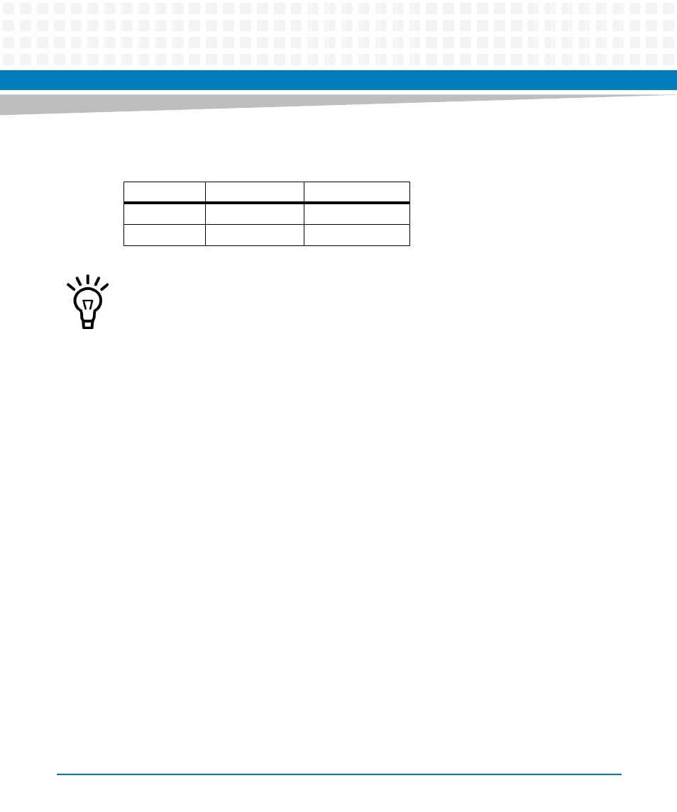
The following table shows the power available when the MVME2502 is installed in either a
three row or five row chassis and when PMCs are present.
2.3.3
Equipment Requirements
The following are recommended to complete a MVME2502 system:
VMEbus system enclosure
System console terminal
Operating system (and/or application software)
Transition module and connecting cables
2.4
Configuring the Board
The board provides software control over most options. Settings can be modified to fit the
user's specifications. To configure, set the bits in the control register after installing the board
in a system. Make sure that all user-defined switches are properly set before installing a
PMC/XMC module. For more information, see
.
Chassis Type
Available Power
Power With PMCs
Three Row
70 W maximum
below 70 W
Five Row
90 W maximum
below 90 W
Keep below power limit. Cooling limitations must be considered.
- MVME2502 Installation and Use (August 2014) MVME2500 Installation and Use Manual (February 2014) MVME2500 ECC Installation and Use (August 2014) MVME2500 Installation and Use (April 2015) MVME2500 Installation and Use Manual (March 2015) MVME2502 Installation and Use (April 2014) MVME2502 Installation and Use (December 2014)