5 vmebus p2 connector, Table 3-7, Vmebus p2 connector – Artesyn MVME2502 Installation and Use (April 2015) User Manual
Page 66: Controls, leds, and connectors
Controls, LEDs, and Connectors
MVME2502 Installation and Use (6806800R96E)
66
3.4.1.5
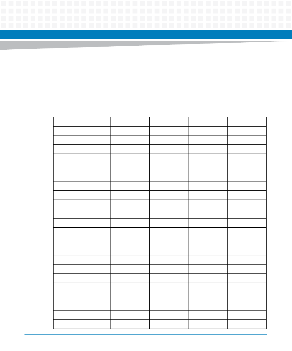
VMEBus P2 Connector
The VME P2 connector is a 160-pin DIN. Row B of the P2 connector provides power to the
MVME2502 and to the upper eight VMEbus address lines and additional 16 VMEbus data lines.
The Z, A, C, and D pin assignments for the P2 connector are the same for both the MVME2502
and MVME7216E/ MVME721E, and are as follows:
Table 3-7 VMEbus P2 Connector
Pin
Row A
Row B
Row C
Row D
Row Z
1
PMC IO 2
+5V
PMC IO 1
GE3_0 +
Serial 1 RX
2
PMC IO 4
GND
PMC IO 3
GE3_0 -
GND
3
PMC IO 6
RETRY
PMC IO 5
GND
Serial 1 TX
4
PMC IO 8
ADDRESS 24
PMC IO 7
GE3_1 +
GND
5
PMC IO 10
ADDRESS 25
PMC IO 9
GE3_1 -
Serial 1 CTS
6
PMC IO 12
ADDRESS 26
PMC IO 11
GND
GND
7
PMC IO 14
ADDRESS 27
PMC IO 13
GE3_2 +
Serial 1 RTS
8
PMC IO 16
ADDRESS 28
PMC IO 15
GE3_2 -
GND
9
PMC IO 18
ADDRESS 29
PMC IO 17
GND
Serial 2 RX
10
PMC IO 20
ADDRESS 30
PMC IO 19
GE3_3 +
GND
11
PMC IO 22
ADDRESS 31
PMC IO 21
GE3_3 -
Serial 2 TX
12
PMC IO 24
GND
PMC IO 23
GND
GND
13
PMC IO 26
+5V
PMC IO 25
I2C DATA
Serial 2 CTS
14
PMC IO 28
DATA 16
PMC IO 27
I2C CLK
GND
15
PMC IO 30
DATA 17
PMC IO 29
GE3_LINK_ LED
Serial 2 RTS
16
PMC IO 32
DATA 18
PMC IO 31
GE3_ACT_LED
GND
17
PMC IO 34
DATA 19
PMC IO 33
GE4_LINK_LED
Serial 3 RX
18
PMC IO 36
DATA 20
PMC IO 35
GE4_A_LED
GND
19
PMC IO 38
DATA 21
PMC IO 37
GND
Serial 3 TX
20
PMC IO 40
DATA 22
PMC IO 39
GE4_3 -
GND
21
PMC IO 42
DATA 23
PMC IO 41
GE4_3 +
Serial 3 CTS
22
PMC IO 44
GND
PMC IO 43
GND
GND
- MVME2502 Installation and Use (August 2014) MVME2500 Installation and Use Manual (February 2014) MVME2500 ECC Installation and Use (August 2014) MVME2500 Installation and Use (April 2015) MVME2500 Installation and Use Manual (March 2015) MVME2502 Installation and Use (April 2014) MVME2502 Installation and Use (December 2014)