4 vmebus p1 connector, Table 3-6, Vmebus p1 connector – Artesyn MVME2502 Installation and Use (April 2015) User Manual
Page 64: Controls, leds, and connectors
Controls, LEDs, and Connectors
MVME2502 Installation and Use (6806800R96E)
64
3.4.1.4
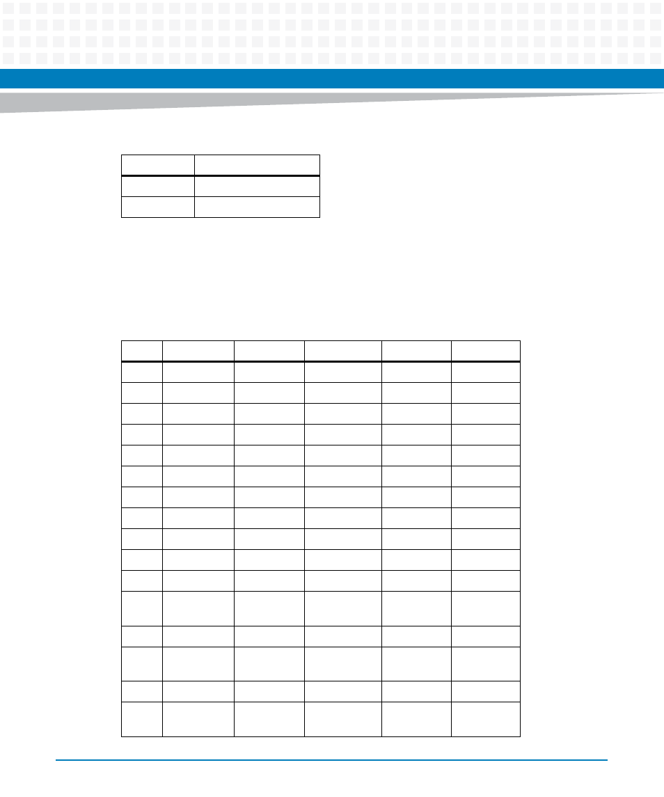
VMEBus P1 Connector
The VME P1 connector is a 160-pin DIN. The P1 connector provides power and VME signals for
24-bit address and 16-bit data. The pin assignments for the P1 connector is as follows:
MTG
Mounting Ground
MTG
Mounting Ground
Table 3-5 USB Connector (J5) (continued)
Pin Name
Signal Description
Table 3-6 VMEbus P1 Connector
Pin
Row A
Row B
Row C
Row D
Row Z
1
DATA 0
BBSY
DATA 8
+5V
NC
2
DATA 1
BCLR
DATA 9
GND
GND
3
DATA 2
ACFAIL
DATA 10
NC
NC
4
DATA 3
BGIN0
DATA 11
NC
GND
5
DATA 4
BGOUT0
DATA 12
NC
NC
6
DATA 5
BGIN1
DATA 13
NC
GND
7
DATA 6
BGOUT1
DATA 14
NC
NC
8
DATA 7
BGIN2
DATA 15
NC
GND
9
GND
BGOUT2
GND
GAP
NC
10
SYSCLK
BGIN3
SYSFAIL
GA0
GND
11
GND
BGOUT3
BERR
GA1
NC
12
DS1
BR0
SYSRESET
+3.3V (not
used)
GND
13
DS0
BR1
LWORD
GA2
NC
14
WRITE
BR2
AM 5
+3.3V (not
used)
GND
15
GND
BR3
ADD 23
GA3
NC
16
DTACK
AM 0
ADD 24
+3.3V (not
used)
GND
- MVME2502 Installation and Use (August 2014) MVME2500 Installation and Use Manual (February 2014) MVME2500 ECC Installation and Use (August 2014) MVME2500 Installation and Use (April 2015) MVME2500 Installation and Use Manual (March 2015) MVME2502 Installation and Use (April 2014) MVME2502 Installation and Use (December 2014)