Table 3-10, Pmc j12/j222 connector, Controls, leds, and connectors – Artesyn MVME2502 Installation and Use (April 2015) User Manual
Page 70
Controls, LEDs, and Connectors
MVME2502 Installation and Use (6806800R96E)
70
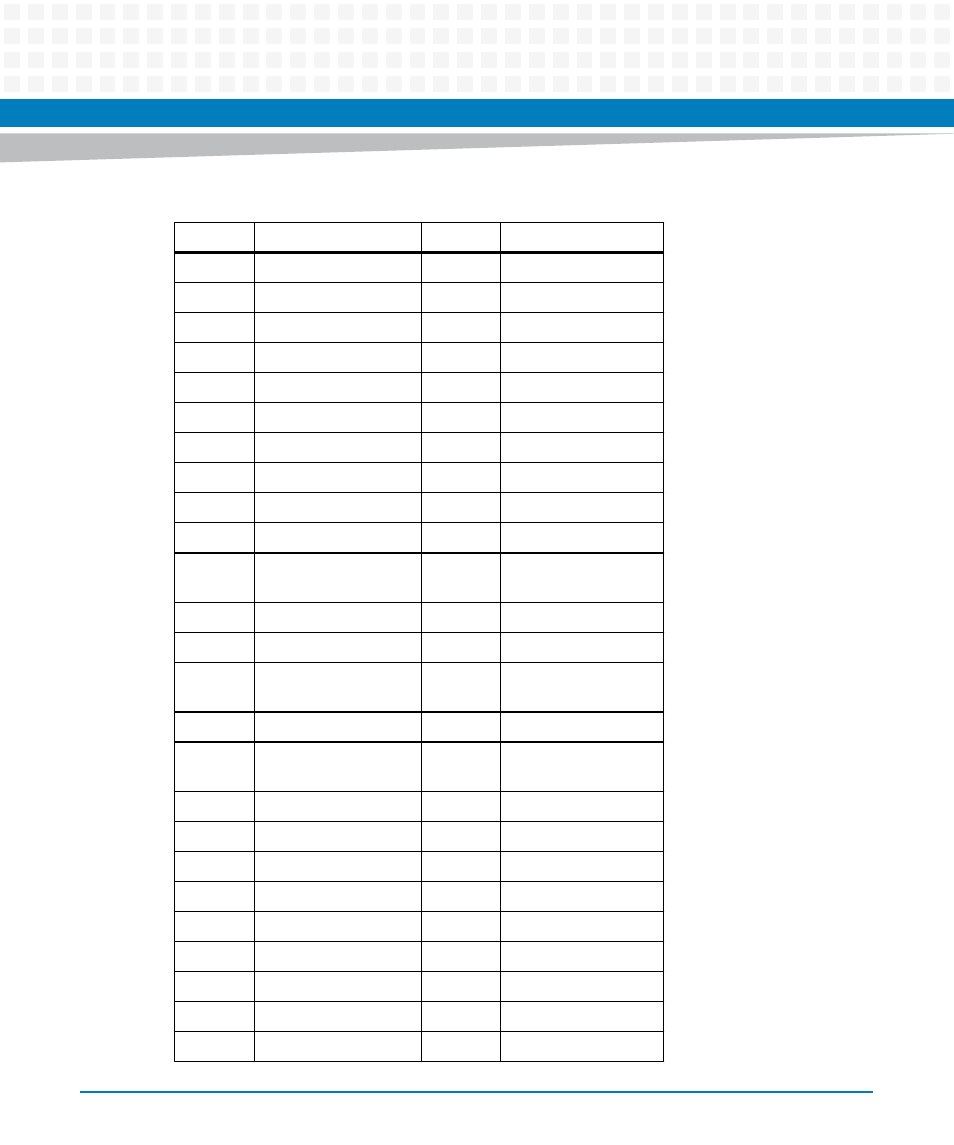
Table 3-10 PMC J12/J222 Connector
Pin
Signal Description
Pin
Signal Description
1
+12V
33
GND
2
JTAG TRST
34
IDSELB
3
JTAG TMS
35
TRDY
4
JTAG TDO
36
+3.3V
5
JTAG TDI
37
GND
6
GND
38
STOP
7
GND
39
PERR
8
NC
40
GND
9
NC
41
+3.3V
10
NC
42
SERR
11
BUSMODE2 (Pulled
UP)
43
CBE1
12
+3.3V
44
GND
13
PCI RESET
45
AD 14
14
BUSMODE3 (PULLED
DWN)
46
AD 13
15
+3.3V
47
M66EN
16
BUSMODE4 (PULLED
DWN)
48
AD 10
17
NC
49
AD 8
18
GND
50
+3.3V
19
AD 30
51
AD 7
20
AD 29
52
REQB
21
GND
53
+3.3V
22
AD 26
54
GNTB
23
AD 24
55
NC
24
+3.3V
56
GND
25
IDSEL
57
NC
This manual is related to the following products:
- MVME2502 Installation and Use (August 2014) MVME2500 Installation and Use Manual (February 2014) MVME2500 ECC Installation and Use (August 2014) MVME2500 Installation and Use (April 2015) MVME2500 Installation and Use Manual (March 2015) MVME2502 Installation and Use (April 2014) MVME2502 Installation and Use (December 2014)