3 custom debugging, 21 rear transition module (rtm), Figure 4-5 – Artesyn MVME2502 Installation and Use (April 2015) User Manual
Page 108: Rtm block diagram
Functional Description
MVME2502 Installation and Use (6806800R96E)
108
4.20.3 Custom Debugging
Custom debugging makes use of the common on-chip processor. Refer to
for details.
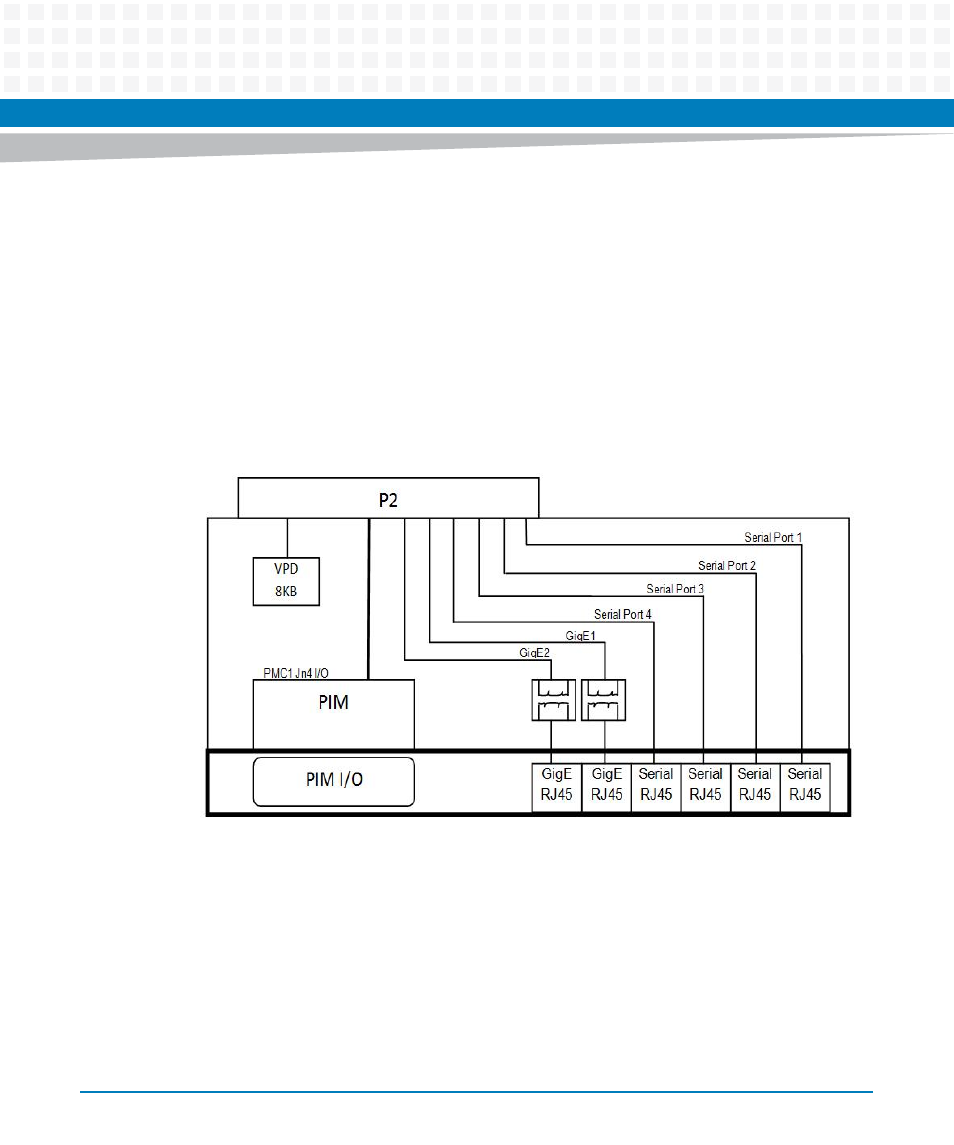
4.21 Rear Transition Module (RTM)
The MVME2502 RTM Block diagram is illustrated below:
The MVME2502 is compatible with the MVME7216E RTM.
Figure 4-5
RTM Block Diagram
This manual is related to the following products:
- MVME2502 Installation and Use (August 2014) MVME2500 Installation and Use Manual (February 2014) MVME2500 ECC Installation and Use (August 2014) MVME2500 Installation and Use (April 2015) MVME2500 Installation and Use Manual (March 2015) MVME2502 Installation and Use (April 2014) MVME2502 Installation and Use (December 2014)