19 real-time clock battery, 20 debugging support, 1 post code indicator – Artesyn MVME2502 Installation and Use (April 2015) User Manual
Page 106: 19 real-time clock battery 4.20 debugging support, Table 4-7, Post code indicator on the led, Functional description
Functional Description
MVME2502 Installation and Use (6806800R96E)
106
4.19 Real-Time Clock Battery
The MVME2502 provides a through hole socket for a CR2325 190mAh lithium battery to
provide backup power for the on-board RTC when primary power is unavailable.
4.20 Debugging Support
The following information shows the details of Artesyn debugging support as applied to the
MVME2502.
4.20.1 POST Code Indicator
The following table shows the LED status of the POST Codes. For the location of the POST Code
LEDs, see
.
Logic 1 means LED is "ON", Logic 2 means LED is "OFF"
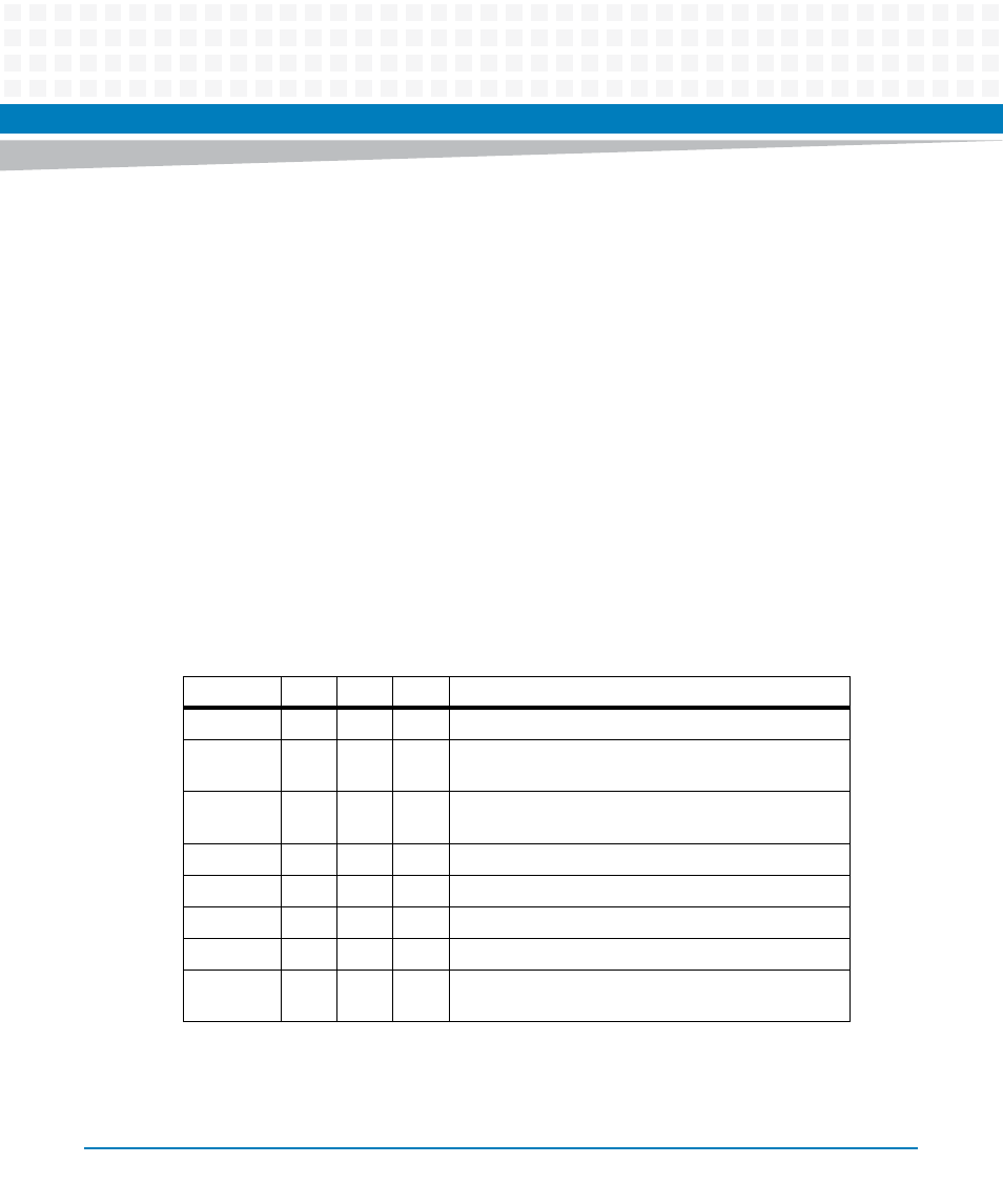
Table 4-7 POST Code Indicator on the LED
Sequence
D33
D34
D35
Description
1
Off
Off
Off
U-boot has been copied from SPI flash to CPU cache.
2
Off
On
Off
Serial console has been initialized, some text is visible
on the terminal.
3
Off
On
On
DDR has been initialized using SPD parameters,
Execution is still in the cache.
4
On
Off
Off
Execution has been relocated to RAM.
5
On
Off
On
PCI has been initialized.
6
On
On
Off
POST routines are finished.
7
On
On
On
Additional SW routines are finished.
8
Off
Off
Off
U-boot prompt is visible on the terminal, can start
loading OS image from USB, Ethernet, SATA SSD, SD.
- MVME2502 Installation and Use (August 2014) MVME2500 Installation and Use Manual (February 2014) MVME2500 ECC Installation and Use (August 2014) MVME2500 Installation and Use (April 2015) MVME2500 Installation and Use Manual (March 2015) MVME2502 Installation and Use (April 2014) MVME2502 Installation and Use (December 2014)