Functional description, 1 block diagram, Figure 4-1 – Artesyn MVME2502 Installation and Use (April 2015) User Manual
Page 83: Block diagram, Chapter 4
Chapter 4
MVME2502 Installation and Use (6806800R96E)
83
Functional Description
4.1
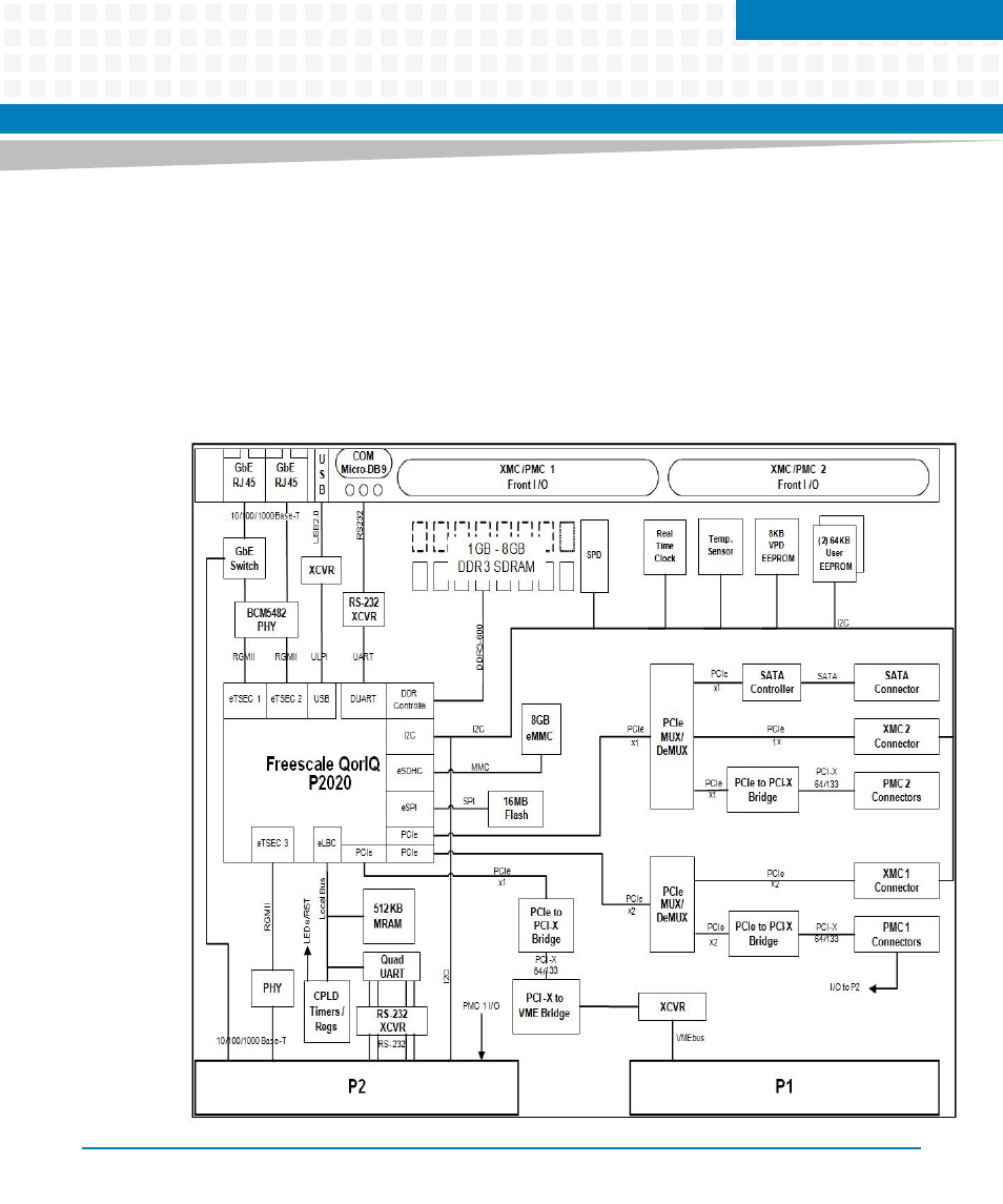
Block Diagram
The MVME2502 block diagram is illustrated in
. All variants provide front panel
access to one serial port via a micro-mini DB-9 connector, two 10/100/1000 Ethernet port
(one is configurable to be routed to the front panel or the rear panel) through a RJ45 connector
and one Type A USB Port. It includes Board Fail LED indicator, user-defined LED indicator and a
ABORT/RESET switch.
Figure 4-1
Block Diagram
This manual is related to the following products:
- MVME2502 Installation and Use (August 2014) MVME2500 Installation and Use Manual (February 2014) MVME2500 ECC Installation and Use (August 2014) MVME2500 Installation and Use (April 2015) MVME2500 Installation and Use Manual (March 2015) MVME2502 Installation and Use (April 2014) MVME2502 Installation and Use (December 2014)