1 reset switch, 3 leds, 1 front panel leds – Artesyn MVME2502 Installation and Use (April 2015) User Manual
Page 58: Figure 3-4, Front panel leds, Controls, leds, and connectors
Controls, LEDs, and Connectors
MVME2502 Installation and Use (6806800R96E)
58
3.2.1
Reset Switch
The MVME2502 has a single push button switch that has both the abort and the reset
functions. Pressing the switch for less than three seconds generates an abort interrupt if there
is firmware that will read the GPIO2 (0xffdf0095) interrupt register. U-boot does not
implement any interrupts and also does not detect the interrupt or display anything when the
button is pressed.
Holding it down for more than three seconds will generate a hard reset. The VME SYSRESET is
generated if the MVME2502 is the VMEbus system controller.
3.3
LEDs
The MVME2502 utilize light emitting diodes (LEDs) to provide a visible status indicator on the
front panel. These LEDs show power failures, power up states, Ethernet link/speed, Ethernet
activity, SATA link and activity and PCIe valid lane status. There are few user configurable LEDs.
Each LED description is necessary for troubleshooting and debugging.
3.3.1
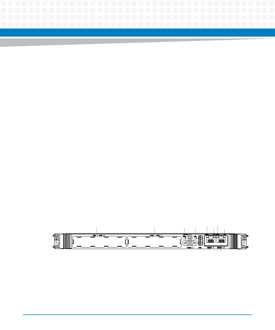
Front Panel LEDs
The front panel LEDs are listed below
Figure 3-4
Front Panel LEDs
PMC/XMC 2
PMC/XMC 1
USER 1 FAIL
SPEED
ACT
ACT
ETH 1
ETH 2
SPEED
- MVME2502 Installation and Use (August 2014) MVME2500 Installation and Use Manual (February 2014) MVME2500 ECC Installation and Use (August 2014) MVME2500 Installation and Use (April 2015) MVME2500 Installation and Use Manual (March 2015) MVME2502 Installation and Use (April 2014) MVME2502 Installation and Use (December 2014)