2 control registers, Table 5-25, Prescaler register – Artesyn MVME2502 Installation and Use (April 2015) User Manual
Page 131: Table 5-26, Control registers
Memory Maps and Registers
MVME2502 Installation and Use (6806800R96E)
131
Prescaler Adjust = 256-(CLKIN/CLKOUT)
CLKIN is the input clock source in MHz, and CLKOUT is the desired output clock reference in
MHz.
The prescaler provides the clock required by each of the three times. The tick timers require a
1 MHz clock input. The input clock to the prescaler is 25 MHz. The default value is set for
0x00E7, which gives 1 MHz reference clock for 25 MHz input clock source.
5.6.2
Control Registers
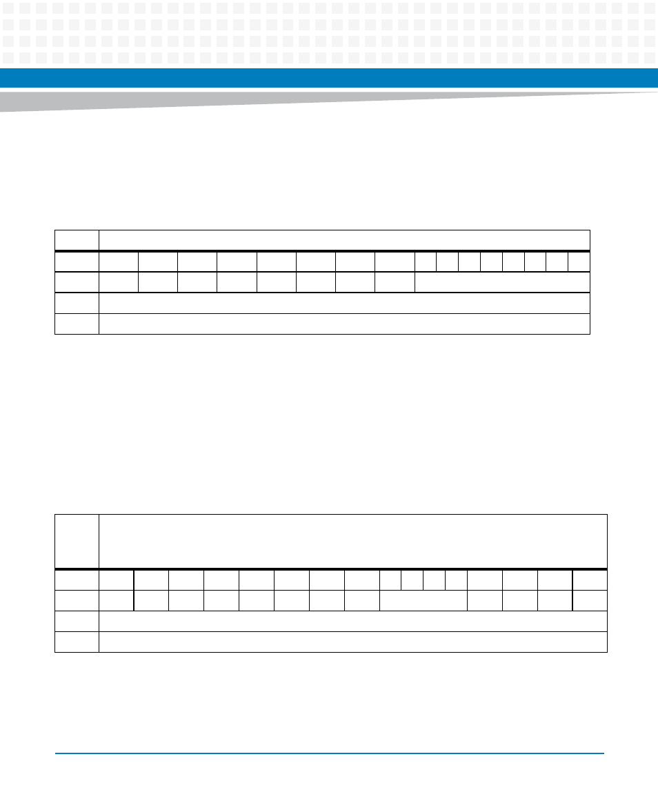
Table 5-25 Prescaler Register
REG
Prescaler Register - 0xFFC80100
Bit
15
14
13
12
11
10
9
8
7
6
5
4
3
2
1
0
Field
RSVD
RSVD
RSVD
RSVD
RSVD
RSVD
RSVD
RSVD
Prescaler Register (8-bits)
OPER
R/W
RESET
0x00e7
Table 5-26 Control Registers
REG
Tick Timer 0 Control Register - 0xFFC80202
Tick Timer 1 Control Register - 0xFFC80302
Tick Timer 2 Control Register - 0xFFC80402
Bit
15
14
13
12
11
10
9
8
7
6
5
4
3
2
1
0
Field
RSVD
RSVD
RSVD
RSVD
RSVD
INTS
CINT
ENINT
OVF
RSVD
COVF
COC
ENC
OPER
R/W
RESET
0x0000
- MVME2502 Installation and Use (August 2014) MVME2500 Installation and Use Manual (February 2014) MVME2500 ECC Installation and Use (August 2014) MVME2500 Installation and Use (April 2015) MVME2500 Installation and Use Manual (March 2015) MVME2502 Installation and Use (April 2014) MVME2502 Installation and Use (December 2014)