2 front panel serial port (j4), 3 usb connector (j5), Table 3-4 – Artesyn MVME2502 Installation and Use (April 2015) User Manual
Page 63: Front panel serial port (j4), Table 3-5, Usb connector (j5), Controls, leds, and connectors
Controls, LEDs, and Connectors
MVME2502 Installation and Use (6806800R96E)
63
3.4.1.2
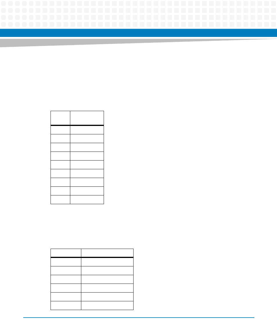
Front Panel Serial Port (J4)
There is one front access asynchronous serial port interface labeled COMM1 that is routed to
the micro mini DB-9 front panel connector. A male-to-male micro-mini DB9 adapter cable is
available under Artesyn part number SERIAL-MINI-D (30-W2400E01A). The pin assignments
for these connectors are as follows:
3.4.1.3
USB Connector (J5)
The MVME2502 uses upright USB receptacle mounted in the front panel.
Table 3-4 Front Panel Serial Port (J4)
Pin
Signal
Description
1
NC
2
RX
3
TX
4
NC
5
GND
6
NC
7
RTS
8
CTS
9
NC
Table 3-5 USB Connector (J5)
Pin Name
Signal Description
1
+5 V
2
Data -
3
Data +
4
GND
MTG
Mounting Ground
MTG
Mounting Ground
This manual is related to the following products:
- MVME2502 Installation and Use (August 2014) MVME2500 Installation and Use Manual (February 2014) MVME2500 ECC Installation and Use (August 2014) MVME2500 Installation and Use (April 2015) MVME2500 Installation and Use Manual (March 2015) MVME2502 Installation and Use (April 2014) MVME2502 Installation and Use (December 2014)